Diagram a - mesh grille diagram b - custom grille – Fusion PP-FR6920 User Manual
Page 2
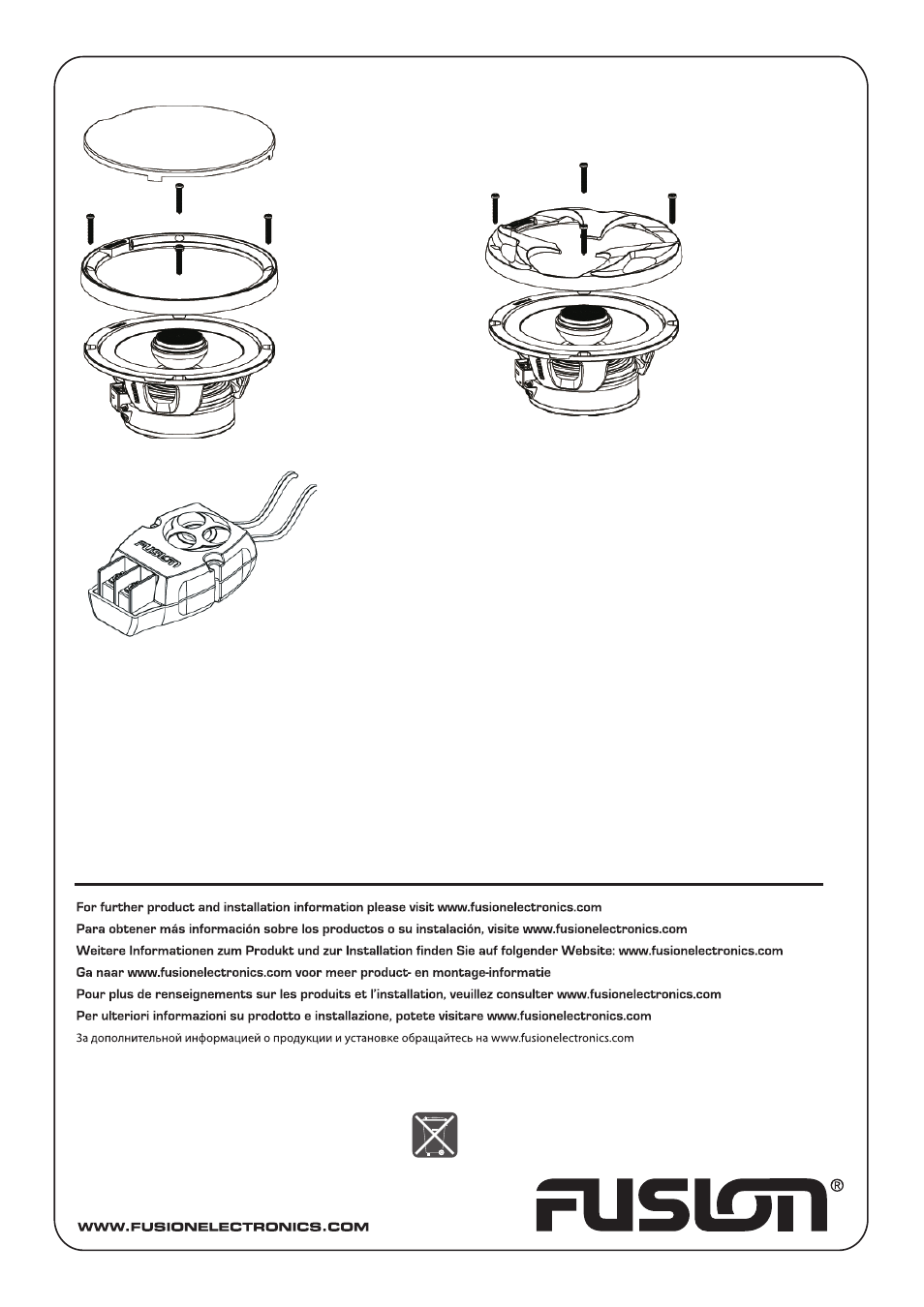
Diagram A - mesh grille
Diagram B - custom grille
WARNING: Do not drill mounting holes with speaker in place, as this could allow drill shavings to damage the voice coil.
Always ensure the audio system is turned off before making any connections to the amplifier, speakers, or source unit.
Failure to do so could result in permanent damage to the audio system.
When wiring the speakers, ensure that the wire is protected from sharp metal objects, and always use rubber grommets
when wiring through metal panels. Ensure all terminals and connections are protected from the vehicle chassis and from
each other.
When connecting the source unit/amplifier and speakers, connect the positive and negative output wire from the source
unit/amplifier, to the corresponding crossover terminals. This will ensure the audio system will be in correct phase.
Crossover Installation
1. Mount the external crossovers in a suitable location, close to the
speakers.
2. Connect the speaker wires from the crossover to the speakers terminals
on the speaker frame (black wires to the black terminal).
3. Connect the tweeter wires from the crossover to the tweeters terminals
on the speaker frame (silver wires to silver terminal).
NB: Striped wire is Positive (Tweeter only).
4. Connect the head unit/source speaker wires to the crossover input
terminals. Ensure you observe correct polarity by connecting the positive
and negative wires to the corresponding terminals.
Silver
Tweeter Output
Black
Speaker Output
Input from source unit
(speaker wires)
Mesh
Grille
Grille
V 2.0
YOU CAN HELP PROTECT THE ENVIRONMENT!
Please remember to respect the local regulations:
Hand in the non-working electrical equipment
to an appropriate waste disposal center.
PUBLISHED BY FUSION ELECTRONICS LIMITED:
© Copyright 2008 by FUSION Electronics Limited.
All rights reserved. Specifications and design are
subject to change without notice.