Cvd-2eq / cvd-2eqa svd-2eq / svd-2eqa, Operations manual, Cvd - 2eq cvd - 2eqa svd - 2eq svd - 2eqa – FSR CVD EQ User Manual
Page 2
CVD-2EQ / CVD-2EqA
SVD-2EQ / SVD-2EQA
1 x 2 COMPOSITE VIDEO LINE DRIVER WITH AND WITHOUT AUDIO
1 X 2 S-VIDEO LINE DRIVER WITH AND WITHOUT AUDIO
OPERATIONS MANUAL
TECHNICAL SPECIFICATIONS:
Video Input
Number/type:
1 Composite on CVD’s & 1 S – Video on SVD’s
Connectors:
1 BNC Female on CVD’s & 1 4-pin d-sub on SVD’s
Level (nominal):
Analog 0.7v p-p
Level (maximum):
2v p-p
Impedance:
75 ohms
Video Output
Number/type:
2 Composite on CVD’s & 2 S – Video on SVD’s
Connectors:
2 BNC Female on CVD’s & 2 4-pin d-sub on SVD’s
Bandwidth:
100 MHz @ -3 dB
Level (nominal):
Unity / User adjustable via knobs for each output
Gain:
Adjustable for cable runs of 1’ to 500’
Impedance:
75 ohms
Audio
Gain:
Unity
Bandwidth:
20 Hz to 20 kHz (+/-0.05 dB)
THD + Noise:
0.01% @ 20 kHz at rated Max Output S/N >98 dB
Noise Floor:
better than 98 dB
Stereo Separation:
-90 dB @ 1 kHz
Audio Input
Number/type:
1 stereo unbalanced
Connectors:
1/8” mini connector & 2 RCA’s
Impedance:
10K Ohms DC coupled unbalanced
Max level:
+6 dBv (.775v = 0dBv)
Audio Output
Number/type:
2 Balanced / Unbalanced Stereo
Connector:
5 Position Captive screw terminal
Impedance:
50 ohm
Maximum Level:
600 ohms: +12 dBv Balanced / +6 dBv Unbalanced
Hi – Z: +14 dBv Balanced / +8 dBv Unbalanced
General
Power:
9v AC, 50/60 Hz: 8 – 14v DC, wallmount AC power supply ( Included )
Enclosure Type:
Metal
Size:
5.125" L X 3.39" W X 1.312" D
Approvals:
Power supply is UL/CSA approved
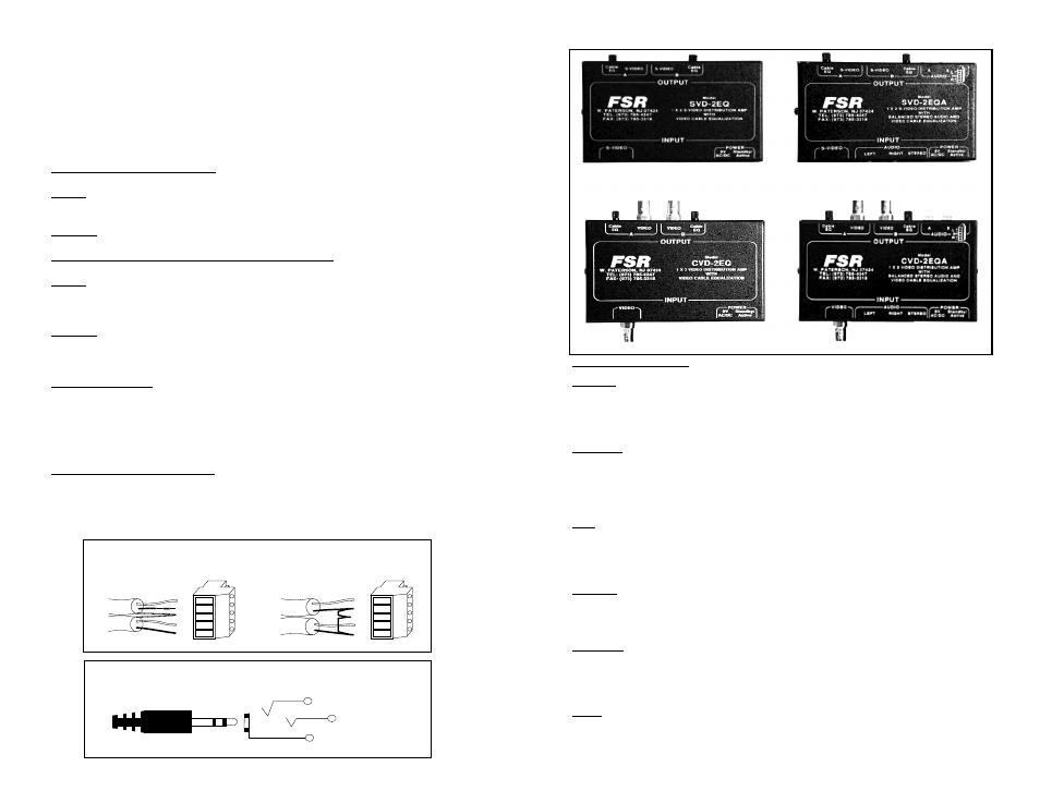
Video Connections
( All Models )
INPUT: Connect the appropriate video source cable to the video input on the amplifier.
Connector type will vary depending on the model number of the amplifier.
OUTPUT: Connect the “A” and “B” video outputs to the display devices.
Audio Connections
( Only on models with audio option )
INPUT: The stereo or mono unbalanced audio source can be connected to either the
stereo mini jack or the right and left RCA input jacks depending on the application. Refer
to the drawing below for pinouts and termination.
OUTPUT: The audio output connector can be configured for either balanced or unbal-
anced audio loads. Connect the output leads to the 5 pin pluggable screw terminals as
shown below. External jumpers may be required depending on the output requirements.
Power Connections:
Attach the 9 VDC power adapter to the two-pin power input jack the amplifier. Plug the
power adapter into a 117 VAC wall outlet. The indicator LED should be yellow when the
amplifier is properly powered and turn green in the presence of a proper video signal from
the source.
Cable Equalization Adjustments:
Cable equalization adjustment potentiometers are provided at each of the video inputs on
the amplifier. Turn each knob while viewing the video sources and adjust for optimum
display quality.
L
+
-
+
-
R
S H
F i g . 1 : O u t p u t C o n n e c t o r W
i r i n g
L
+
-
+
-
R
S H
B a l a n c e d W
i r i n g
U n b a l a n c e d W
i r i n g
J u m
p e r
F i g . 2 : U n b a l a n c e d I n p u t C o n n e c t o r P i n o u t
T i p = L e f t
R i n g = R i g h t
S l e e v e = G n d
CVD - 2EQ
CVD - 2EQA
SVD - 2EQ
SVD - 2EQA