FSR DV-HXT-2 User Manual
Page 7
7
Set up and Video Connection
Step 1: Ensure the digital video/audio source and display is turned off
Step 2: Connect digital HDMI cable
Step 3: Connect a UTP cable to Digital RGB port of TX module and connect the
other end of the cable to Digital RGB port of RX module
Step 4: Connect a second UTP cable to DDC port of TX module and connect the
other end of the cable to DDC port of RX module
Step 5: Connect power adapter to transmitter (TX) module of DV-HXT-2
Step 6: Connect power cord to the power adapter and plug in to power outlet
Step 7: Power up the display
Step 8: Power up the source
Step 9: Set 1080p or highest resolution
Step 10: Set up rotary switch value referencing to EQ switch set up table according
to UTP cable length
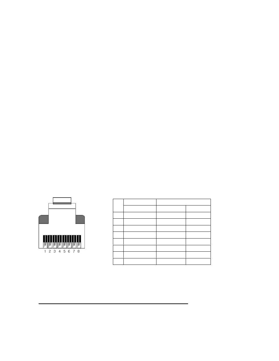
UTP Cable connection
DV-HXT-2 follows TIA/EIA-568-B specification.
Please refer to the picture and table for correct connection.
For the high resolution above 1080p or WUXGA, CAT6E 550MHz unshielded solid
core by Liberty Wire & Cable is recommended.
Connection of UTP Cable
No matter what the length is, cut two UPT cables to exactly the same length
Use two cables as a pair: different colors are useful
C
C
a
a
u
u
t
t
i
i
o
o
n
n
:
:
D
D
o
o
n
n
o
o
t
t
c
c
o
o
n
n
n
n
e
e
c
c
t
t
w
w
i
i
t
t
h
h
i
i
n
n
t
t
e
e
r
r
n
n
e
e
t
t
o
o
r
r
e
e
a
a
r
r
t
t
h
h
n
n
e
e
t
t
d
d
e
e
v
v
i
i
c
c
e
e
s
s
TIA/EIA-568B
Signal
Pin Wire color
Digital RGB
DDC
1
Orange/ White
TMDS Data2+
+5V
2
Orange
TMDS Data2-
HPD
3
Green/ White
TMDS Data1+
Ground
4
Blue
TMDS Data0+
CEC
5
Blue/ White
TMDS Data0-
Ground
6
Green
TMDS Data1-
DDC data
7
Brown/ White
TMDS Clock+
Ground
8
Brown
TMDS Clock-
DDC Clk