Freeplay Energy Weza User Manual
Page 2
Q: Is using the Step Input the only means to charge my FreeCharge?
Q: How long will it take to charge my FreeCharge from the wall socket with the AC/DC charging
adapter?
Q: Can I charge my 12V DC device while the FreeCharge is being charged either through the DC
input or via the Crank?
Q: What materials are used in the FreeCharge and are they recyclable?
Q. How long will a fully charged battery retain its charge?
Q. Will I damage the FreeCharge if I crank the pedal too fast?
Q: Can I over-crank the unit - does it ever stop you from cranking?
Q: What type of rechargeable battery is used in the FreeCharge?
Q: How long does the warranty last?
Q: Can I leave my FreeCharge charging from an AC wall charger all the time and unplug it when I
need to use it?
Q: Should I discharge the FreeCharge's internal battery before recharging?
TROUBLESHOOTING
Symptom
A: No. The FreeCharge can also be charged from either a DC or AC power source.
A: It will take approximately 8 hours to fully charge the FreeCharge.
A: Yes.
A: The casings are made of polypropylene and glass-filled nylon. The transmission is made of a
combination of acetyl, glass-filled nylon and aluminum, while the input levers, pedal and stabilizer arms
consist of a glass-filled nylon. All plastic materials used are thermoplastics and can be recycled. The
FreeCharge contains a non-spill rechargeable Lead Acid battery, which needs to be recycled according to
regulations stipulated by your local authority. Please consult your user manual or contact the Freeplay
Customer Support Center for more advice.
A: The battery will self-discharge at 5% per month when the unit is stored at a temperature of 68 F. The self-
discharge rate increases with an increase in ambient temperature.
A. No, the faster you crank the more energy you store in the internal battery.
A. No, you cannot over-crank the internal mechanism. It consists of simple gearbox, which drives an
alternator, providing power to the internal battery.
A. The FreeCharge incorporates a non-spill rechargeable 12 V 7 Amp hour Lead Acid battery.
A. The FreeCharge has a 2 year warranty
A: The FreeCharge should not be left on charge for longer than 24 hours.
A: No. The FreeCharge contains a non-spill Lead Acid battery, which does not require total discharge before
recharging. Leaving a Lead Acid battery in a fully discharged state for an extended period of time will cause
damage to the battery and limit its life.
The display bar does not illuminate to show that the FreeCharge is receiving a charge.
°
# The FreeCharge will not accept a Charge from a DC source.
# The FreeCharge will not accept a charge from the AC/DC adapter.
Symptom
The display bar does not illuminate after plugging in and switching on the AC/DC adapter
The DC source has insufficient power to charge
the FreeCharge or is faulty. The FreeCharge will
not accept a charge from a DC source that has a
voltage lower than 13 volts.
Disconnect the FreeCharge from the DC source.
Charge the FreeCharge by using either the Step
Input or the AC charging adapter.
The voltage of the DC source is too high for the
FreeCharge (over 25 Volts) and has burnt out the
charge electronic circuitry.
Replace the control panel unit.
A faulty charging cable
Replace charging cable
Incorrect polarity
Check polarity
Possible Cause
Solution
Possible Cause
Solution
# The FreeCharge cannot operate or charge an appliance from is cigarette lighter DC output socket.
Symptom
The appliance does not operate.
A faulty AC adapter
Check or Replace the AC adapter
# The FreeCharge cannot jump start a boat or vehicle's engine.
Symptom
The engine is not turning over
**Cranking Amps are a measure of how much power a battery can supply to start an engine at 32º F.
The Input arm is either stuck or has no resistance.
#
The Step Input does not work
Symptom
The FreeCharge's internal battery is damaged
Replace the internal battery
The FreeCharge's battery is not sufficiently
charged
Recharge the FreeCharge using an AC or DC
source. After charging confirm the charge status
by pressing the “Display Battery Level” button.
Alternatively, disconnect the FreeCharge’s internal
battery with the ‘battery disconnect switch’ and use
the step charge input to recharge the receiving
battery directly.
The engine receiving is in poor condition.
Replace the receiving battery.
The engine's cranking amps requirements
exceeds the FreeCharge's jump start capability **
It is not possible to jump start this particular engine
using FreeCharge.
The FreeCharge's internal battery is discharged.
Recharge the FreeCharge using, either an AC
source, DC source or the step input. After charging
confirm the charge status by pressing the “Display
Battery Level” button.
Possible Cause
Solution
Possible Cause
Solution
Possible Cause
Solution
Internal gears and mechanism are damaged.
Consult the Service manual or contact the
Freeplay Customer Service Center.
# The display bar does not work
Symptom
The display bar does not illuminate.
The FreeCharge is totally discharged.
Recharge the FreeCharge.
The FreeCharge internal battery is damaged.
Replace the internal battery.
Possible Cause
Solution
considerable resistance due to the alternator magnets).
Loosen the 4 bolts and remove the alternator, drawing its 3 wires from the conduit to the battery
compartment.
Pull the rotor cup off the base plate of the replacement alternator. Bolt the base plate to its mountings on the
left inner casing. Feed the 3 wires through to the battery compartment and reconnect at the connector block
in the battery compartment
The order of connection does not matter. Replace the rotor cup
. Replace the other components by reversing the disassembly procedure.
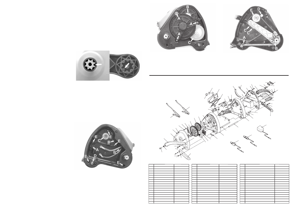
Remove the right input lever and right stabiliser arm. Remove the right side outer casing by removing its 5
(Figure 8, A).
(figure 9, C)
7. Replacing the Drive Shaft Assembly or the Drive Belt and Spring
bolts. Remove the battery and control panel, as described previously.
Remove the 5 bolts which lock the inner casings
and the circlip and washer on the input shaft
Disconnect the 3 alternator wires at the connector block
. Pull away the right inner
casing feeding the alternator wires through their conduit and leaving the internal parts assembled in the left
inner casing. Unhook the spring from the stabilizer arm pivot shaft
and pull the drive shaft
assembly together with the attached belt and spring free
Remove 2 bolts
to
detach the belt together with the spring from the drive shaft assembly. Reverse this procedure to re-
assemble making sure that the belt is tracked correctly under the belt retaining bush
and over
the toothed input pulley
before re-hooking the spring end to the stabilizer pivot shaft
. Make sure that the input lever arms are indexed correctly to the drive shaft assembly when re-
assembling
.
(figure 8, E)
(figure 8, C).
(figure 8, A)
(figure 10, A)
(Figure 10, B).
(figure 10, C)
(figure 10, D)
(figure 10, E)
(figure 10,
A)
(figure 7)
9. SERVICE MANUAL
DISASSEMBLING THE FREECHARGE WEZA
PART REPLACEMENT
3. Replacing the Battery
5. Replacing Gear Components
6. Replacing the Alternator
Sequence of disassembly
NOTE:
The FreeCharge is supplied with a tool kit to enable disassembly.
- these are defined when viewing the FreeCharge from its pedal end.
The input levers and stabilizer arms must first be removed before the outer, and then the inner casings
can be opened.
The gearbox and alternator are located under the outer left casing.
The battery and bolts to release the control panel assembly are located under the right outer casing.
The 5 bolts to split the inner casings
are located in the inner right casing (battery
compartment) and are accessed by removing the right outer casing.
The drive shaft assembly, drive belt and return spring are located within the inner casings.
(Figure 11)
Left and right components
#
#
#
#
#
#
#
#
DO NOT
1. Replacing an Input Lever and Pedal
2. Replacing a Stabilizer Arm
4. Replacing the Control Panel
remove the stabilizer arm pivot shaft
from the main assembly if you
are not intending to split the 2 inner casings, as the internal spring is attached to this shaft
.
The input levers and splined drive shaft have an indexing tooth (which has a rounded tip) and should only
be assembled in their correct indexed orientation
.
Remove the input lever by unscrewing 2 bolts, one located at the pivot end of the input lever and the other
at the pedal end. Work the input lever off the drive shaft and the pedal shaft. The pedal consists of 2 halves
which can be removed once one of the input levers has been removed. The input levers and splined drive
shaft have an indexing tooth and should only be re-assembled in their correct indexed orientation
.
The pedal halves should be assembled with the diamond pattern facing upward.
Remove a stabilizer arm by removing 2 bolts. Work the stabilizer arm off the stabilizer pivot shaft and the
stabilizer locking shaft. DO NOT remove the stabilizer arm pivot shaft
from the main assembly if
you are not intending to split the 2 inner casings, as the internal spring is attached to this shaft.
Reverse this procedure to re-assemble.
Remove the right input lever and right stabilizer arm as described above.
Remove the right side outer casing by removing its 5 bolts.
The casing will come away partly, as the battery is attached to it. The battery should now be visible and its 2
terminals should be accessible. Disconnect the wires from the battery by undoing the bolts and remove the
battery.
To insert a new battery, reverse the procedure above. Ensure that the wires are connected to the correct
terminals. The red wire to the positive terminal and the black wire to the negative terminal.
Remove the battery as described previously. Remove the leads to the battery disconnect switch terminals
located in the right outer casing. Disconnect the 3 alternator wires at the connector block
and
release the wires from their cleats. Remove the 2 bolts that hold the control panel in place
. The
control panel unit can now be pulled free, feeding the cables and the 3 alternator wires through the aperture
in the right inner casing.
The control panel is replaced by reversing this procedure.
Remove the left input lever and left stabilizer arm as described previously. DO NOT remove the stabilizer
arm pivot shaft from the main assembly if you are not intending to split the 2 inner casings, as the internal
spring is attached to this shaft.
Remove the left outer casing by removing 5 bolts.
Remove the gear plate by removing 3 bolts
. The secondary gear can now be removed or
replaced. Remove the circlip from the input shaft
o remove or replace the input gear.
Remove the right and left input lever and the right and left stabilizer arms as described above. DO NOT
remove the stabilizer arm pivot shaft from the main assembly if you are not intending to split the 2 inner
casings, as the internal spring is attached to this shaft.
Remove the right outer casing by removing 5 bolts.
Disconnect the battery as described above.
Disconnect the 3 alternator wires at the connector block
.
Remove the left outer casing by removing 5 bolts.
Remove the gear plate by removing 3 bolts
. Remove the secondary gear. To gain access to
the 4 bolts that fasten the alternator to the left inner casing, pull the rotor cup off its base plate
.
Do not lever the rotor cup off, but pull in a straight line so as not to cause damage. (There will be
(Figure 8, D)
(Figure 10, A)
(Figure 7)
(figure 8, D)
(figure 8, A)
(figure 8, B)
(Figure 9, A)
(Figure 8, A)
(Figure 9, A)
(figure 9, C)
(Figure 7)
(Figure 8, E)
(figure 9, B) t
Figure 7
Figure 10
Figure 9
The electronic circuitry is damaged.
Contact the Freeplay Customer Service Center.
002
006
206
210
102
208
206
104
106
108
008
024
206
210
022
218
020
310
216
120
118
122
124
308
034
204 202
218
206
206
206
208
208
208
032
028
312
026
030
104
214
112
114
116
040
042
306
304
302
014
010
204
206
208
206
208
202
036
018
016
316
318
314
012
038
110
212
110
004
Figure 11
KEY
002
004
006
008
010
012
014
016
018
020
022
024
026
028
030
032
034
PART NAME
Left Input Lever
Left Stabilizer Arm
Left Outer Casing
Left Rear Foot
Left Front Foot
Left Inner Casing
Control Panel Gasket
Right Inner Casing
Right Front Foot
Right Rear Foot
Right Outer Casing
Right Input Lever
Battery Switch Cover
Pedal Top
Pedal Shaft
Pedal Bottom
Right Stabilizer Arm
PART No.
114-ILL-GOL
012-SL-GOL-A
002-COL-GOL
010-FBL-GOL
008-FFL-GOL
001-CIL-GOL-A
032-PG-GOL
003-CIR-GOL-A
009-FFR-GOL
011-FBR-GOL
004-COR-GOL
115-ILR-GOL
043-BSG-GOL
120-PT-GOL
118-LB-GOL
121-PB-GOL
013-SR-GOL-A
KEY
036
038
040
042
102
104
106
108
110
112
114
116
118
120
122
124
202
PART NAME
Stabilizer Locking Shaft
Stabilizer Pivot Shaft
Positive Clamping Nut
Negative Clamping Nut
Gear Plate
Secondary Gear Bearing
Secondary Gear
Input Gear
Alternator
Input Shaft
Clutch Bearing
Toothed Pulley
Drive Belt
Input Shaft Washer
Drive Shaft Assembly
Return Spring
Bolt
PART No.
016-SS-GOL
016-SS-GOL
038-PNG-GOL-RED
038-PNG-GOL-BLK
005-GP-GOL
144-SGB-GOL
142-SGP-GOL-A
140-IGH-GOL-A
100-ALT-GOL
103-IS-GOL
112-CB-GOL
111-TP-GOL
107-TB-GOL
125-ISW-GOL
102-DS-GOL-A
104-TS-GOL
200-CS-BH-M10x25
KEY
204
206
208
210
212
214
216
218
302
304
306
308
310
312
314
316
318
PART NAME
Serrated Washer
Bolt
Serrated Washer
Washer
Countersunk Bolt
Circlip
Circlip
Bolt
Positive Jumper Cable
Negative Jumper Cable
Control Panel Unit
Battery
Battery Switch Lead
Battery Switch
AC/DC Charging Adapter
DC Charging Cable
Selectable DC Output Adapter (not supplied)
PART No.
200-W-S-M10
200-CS-M6x20
200-W-S-M6
200-W-M6
200-CS-C-M4x12
200-CC-EX-36
200-CC-EX-23
200-CS-M6x10
017-JC-GOL-A-RED
017-JC-GOL-A-BLK
030-IP-GOL-A
300-BAT-GOL
300-BLS-GOL
044-BS-GOL
600-ACDC-GOL
601-DCCC-GOL
602-SVDCO-GOL
Figure 8