Fluke Biomedical 07-440 User Manual
Page 9
Operation
Setup
2
2-3
ZERO SET
1. Place the supplied 3 mm aperture in position under the photohead, in the depression over the filter
light source WITH THE FLAT SIDE UP.
2. Position the ZERO Control fully counterclockwise.
3. Apply pressure to the measurement arm as indicated (PRESS HERE) until it makes firm contact
with the aperture. The display should read 0.010 to 0.20 (positive).
4. Turn the ZERO control clockwise until the minus sign (located just above the left hand digit) flashes
on and off, indicating an exact zero condition.
BAUD RATE SELECTION
The unit is shipped with the baud rate factory set for 9600, 8 data bits with one stop bit. Use the following
procedure to change the baud rate and/or data bits, stop bit, and parity combination.
1. Remove the four (4) screws on white panel containing the power switch.
2. Carefully slide the panel forward to gain access to the dip switches.
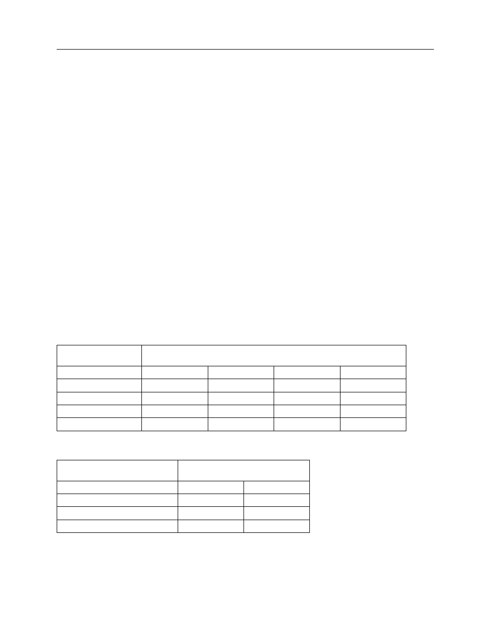
3. Position SW1-3 to SW1-6 as indicated in Table 2-1 for the desired baud rate selection.
4. Position SW1-1 and SW1-2 as indicated in Table 2-2 for the desired data bit, stop bit, and parity
combination.
5. RS-232 Cable Connections are as follows:
a. Pin 2: Transmit
b. Pin 3: Receive (Not Used)
b. Pin 7: Signal Ground
Table 2-1. Baud Rate Selection
Switch SW1 - Position
Baud Rate
6 5 4 3
300 OFF
OFF
ON
OFF
1200 OFF ON OFF OFF
2400
ON OFF OFF OFF
4800 OFF ON ON OFF
9600 OFF ON ON ON
Table 2-2. Data Bit, Stop Bits, and Parity Selection
Switch SW1 - Position
Selection
1 2
8 DATA, 2 STOP, NO PARITY
OFF
OFF
8 DATA, 1 STOP, NO PARITY
OFF
ON
7 DATA, 2 STOP, NO PARITY
ON
OFF
7 DATA, 1 STOP, NO PARITY
ON
ON