3 testing procedures – Fluke Biomedical 84-350 User Manual
Page 7
Introduction
Description
1
1-3
Vertical Plane Target
A group of 0.1 mm parallel wires are positioned 1 cm apart down the center of the phantom in a vertical
plane (Figure 1-5). When scanned from the top, this target enables measurement of vertical linearity,
depth calibration and gain as a function of depth.
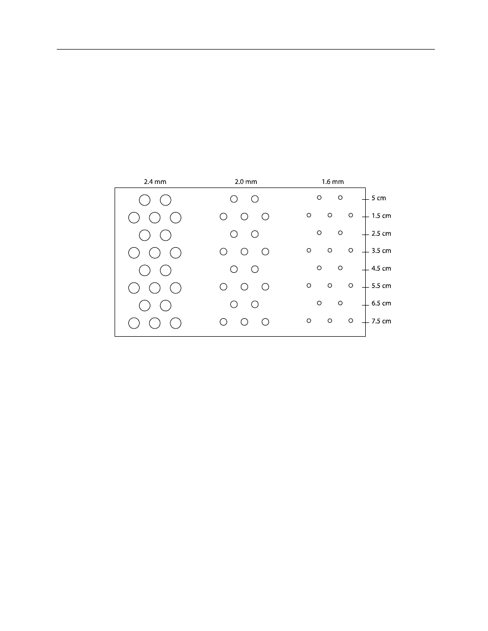
Scatter Targets
Three groups of cylinders with diameters of 1.6, 2.0 and 2.4 mm are arranged in a specified pattern at a
designated position in the phantom. The cylinders have a backscatter that is approximately 15 dB lower
than the background, and enable the identification of a system's anechoic mass detectability threshold.
Figure 1-4.
Calibrated Volumetric Test Object
One mass with a specific calibrated volume is embedded at one end of the phantom approximately 3 cm
deep. The backscatter within the test subject is approximately 9dB lower than the background. This target
is designed for evaluation of spatial measurements and volumetric calculations.
1.3 Testing Procedures
Dead-Zone Identification
The transducer should be placed firmly above the near field resolution target and perpendicular to the
wires. Dead zone or the ring down distance can be defined as that distance between the transducer's
face and the closest wire target to be resolved from the reverberation. If the first target to be resolved is at
4 mm, then the dead zone distance is "something less than 4 mm."