Fluke Biomedical 07-611 User Manual
Page 11
Operation
X-Ray Tube Focal Spot Measurements
2
2-5
[
]
[
]
[ ]
[
]
9. On the radiograph of the magnification insert, measure the distance (in centimeters) between the
images of the holes of the magnification insert using the ruler.
10. Divide image hole separation by 1 cm, the separation of the holes in the magnification insert.
Calculate the magnification using the following formula:
image hole separation
1
cm
- 1 = Magnification
For example, assume the image hole separation was measured as 3.20 cm
3.20 cm
1
cm
- 1 = 2.20
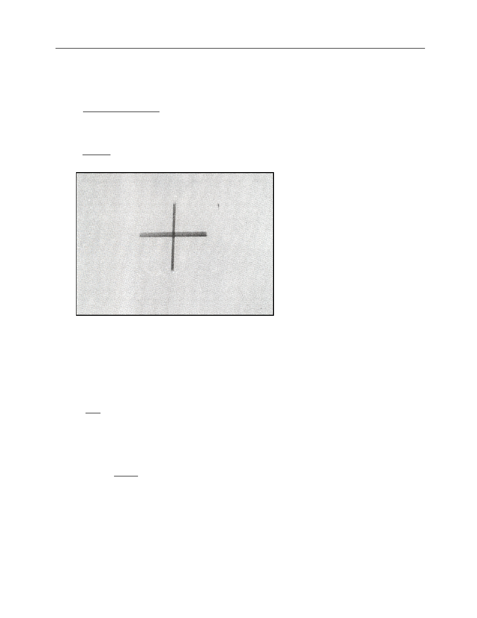
Figure 2-8. Slit Image Parallel and Perpendicular to the Anode-Cathode Axis
11. Measure across the middle of each slit image using the magnifier lens (with a built-in graticule). The
measurement across the band parallel to the anode-cathode axis is related to the width of the focal
spot. The measurement of the band perpendicular to the anode-cathode axis is related to the
"length of the focal spot.
12. To determine focal spot size, divide the measured width and length by the magnification factor. For
example, if the measured length of the slit image is 1.76 mm then:
1.76
2.20
= 0.80 mm (length of focal spot)
13. Since many mammographic x-ray tubes are mounted at an angle (the anode-cathode axis is not
parallel to the image receptor), it is necessary to correct the focal spot length measurement for the
tube assembly tilt angle. The following formula is used:
Sin (A)
L = F
Sin (T +
A)
where
L = the actual focal spot length
F = the users measured length
A = x-ray tube anode (target) angle (Provided by the x-ray tube manufacturer.)