Wiring installation – Flowserve NRS 1-42 User Manual
Page 10
10
UNITRONIC
®
is a registered trademark of LAPP Kabelwerke GmbH, Stuttgart
Wiring
Installation
NRS 1-42
Tool
Installation on mounting rail
1. Clip level switch onto mounting rail 35 x 15 mm
(DIN EN 50022).
2. Align level switch, fig. 11, fig. 12
■
Screwdriver (5.5/100)
Wiring diagram
See wiring diagrams on page 3 and 4.
Note that screened multi-core twisted-pair control cable is required, e. g. UNITRONIC
®
BUS CAN 2 x 2 x ...
2
or RE-2YCYV-fl 2 x 2 x ...
2
.
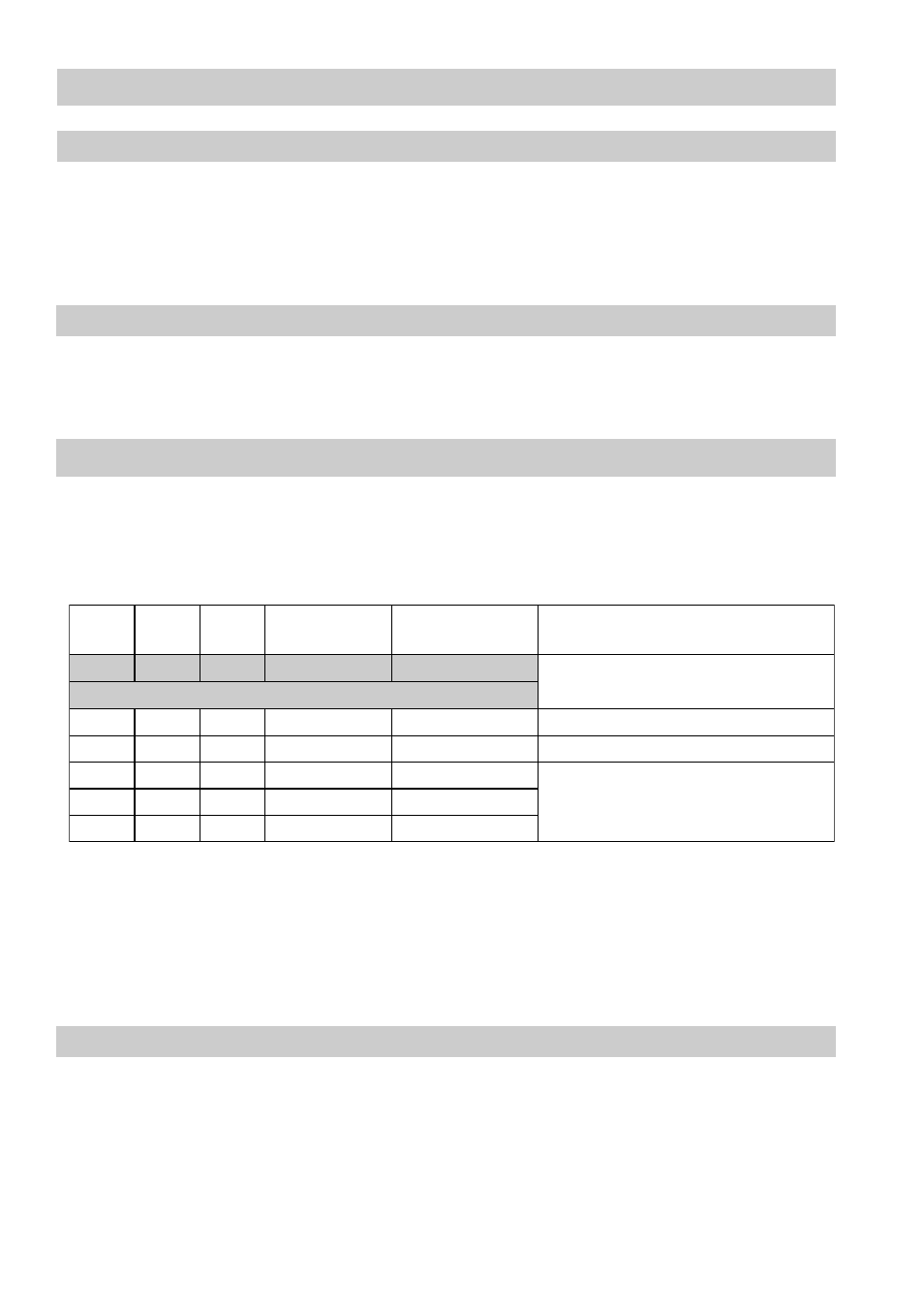
The baud rate (data transfer rate) dictates the cable length between the bus nodes and
the total power consumption of the measuring sensors dictates the conductor size.
The baud rate is set via a code switch. Reduce baud rate if cable is longer than
specified in the table. Make sure that all bus nodes have the same settings.
To protect the switching contacts fuse circuit with 2.5 A (anti-surge fuse) or according
to TRD regulations (1.0 A for 72 hrs operation).
When a max. cable length of 1000 m is desired, make sure to modify the baud
rate accordingly. Refer to pages 23 and 24 for more details.
8
S
9
S
0
1
S
e
t
a
r
d
u
a
B
h
t
g
n
e
l
e
l
b
a
C
s
r
i
a
p
f
o
r
e
b
m
u
N
m
m
[
e
z
i
s
r
o
t
c
u
d
n
o
c
d
n
a
2
]
F
F
O
N
O
F
F
O
s
/
t
i
B
k
0
5
2
m
5
2
1
4
3
.
0
x
2
x
2
g
n
i
t
t
e
s
y
r
o
t
c
a
F
N
O
N
O
F
F
O
s
/
t
i
B
k
5
2
1
m
0
5
2
5
.
0
x
2
x
2
F
F
O
F
F
O
N
O
s
/
t
i
B
k
0
0
1
m
5
3
3
5
7
.
0
x
2
x
2
N
O
F
F
O
N
O
s
/
t
i
B
k
0
5
m
0
0
5
n
o
t
n
e
d
n
e
p
e
d
,
t
s
e
u
q
e
r
n
o
n
o
i
t
a
r
u
g
i
f
n
o
c
s
u
b
F
F
O
N
O
N
O
s
/
t
i
B
k
0
2
m
0
0
0
1
N
O
N
O
N
O
s
/
t
i
B
k
0
1
m
0
0
0
1