Operation, alarm and test – Flowserve NRA 1-3 User Manual
Page 16
6
Function of keys
Key :
Reduce value –, browse
Key 3:
Increase value +, browse
Key (E): Press briefly: Call up/Execute menu // Continue / Save settings
Key (E): Press longer: Return to menu, cancel input
Key + 3: Press longer: Reset/Delete values (e. g. alarm list + maintenance interval)
LEDs 1 – 3
LED :
Steam loss
LED :
Banking-up of condensate
LED 3:
Measuring electrode NRG 6-7 defective (short circuits, parting of a cable).
Measuring electrodes NRG 6-9 are not monitored.
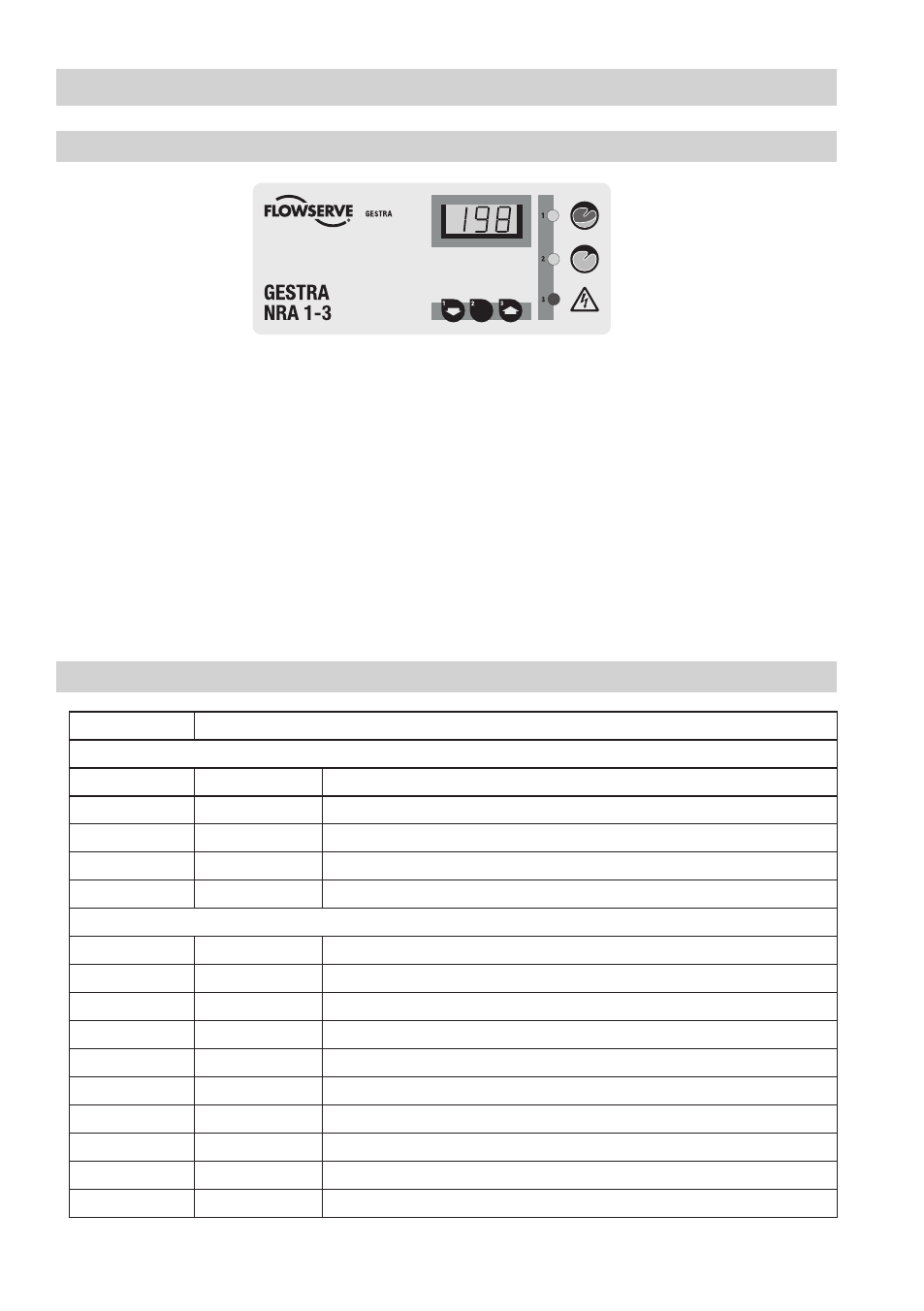
Operation, Alarm and Test
Specification of keys and displays
E
Fig. 6
Key to codes on seven-segment display
Code
Meaning
The following codes can appear on the seven-segment display even if no key is being pressed:
SYS
System
SYS changes with plant temperature in °C
E.0
Error
Incorrect configuration due to inadmissible code switch setting
E.0
Error
In mode and 7 the settings for banking-up of condensate is not finished
E.03
Error
Maintenance interval (6 months) elapsed
C.0 – C.6
Channels - 6
Indication of measuring channel
If the E key is pressed:
HIS
History
Alarm list detailing old alarms
InT
Interval
Remaining time of maintenance interval
CAL
Calibration
Channel calibration in mode
dtC (mode , 7)
Delta TC
Admissible deviation from condensate temperature in steam trap
dtS (mode , 6)
Delta TS
Admissible deviation from plant temperature
tSt
Test
LEDs and all segments are illuminated
ALL
All channels
Channel selection when calibrating / setting
C.0 – C.6
Channels - 6
Indication of measuring channel
don
Done
Confirmation of input when setting parameters
clr
Clear
Confirmation of clear command (interval, alarm)