Accord controls – Flowserve Accord Centura Analog Output Options User Manual
Page 2
Flowserve Corporation
1350 N. Mountain Springs Parkway
Phone: 801 489 2234
Flow Control Division
Springville, Utah 84663-3004
Facsimile: 801 489 2228
www.flowserve.com
Accord Controls
Installation, Operation and Maintenance Instructions
FCD ACAIM0073-00 (AC-73) 06/04
Page 2 of 2
© 2004, Flowserve Corporation, Printed in USA
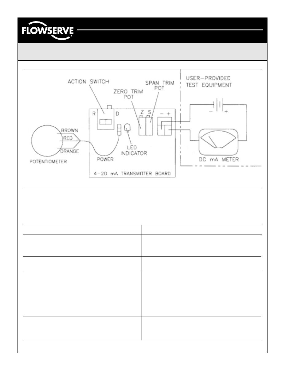
Figure 1 – 4-20 mA Transmitter Diagram
Probable Cause/Solution
Potentiometer is out of adjustment (see “Resistive Feedback
Calibration” or 4-20 mA Current Transmitter Calibration”
steps 2-4).
Zero or span trim potentiometer is out of adjustment
(see 4-20 mA Current Transmitter Calibration).
Circuit Board LED not lit:
1. Loose or shorted signal connection (no loop power).
2. Controller board not responding (replace board).
Circuit Board LED lit:
1. Potentiometer disengaged.
2. Defective potentiometer or controller board. Replace
defective component.
Input signal not linear. Linkage or drive mechanism is
introducing non-linearity. Zero span trim potentiometer is
out of adjustment (see 4-20 mA Current Transmitter Calibration).
Problem
Output is not continuous throughout actuator/valve stroke
(experience a band of max. output)
Transmitter does not out 4 or 20 mA at desired end of travel.
Transmitter module does not provide current signal or provide
constant signal.
Output not linear or does not track valve position/rotation
Troubleshooting