Flowserve CPL Series CENTURA User Manual
Page 4
LME0009-1 (Auto-39) 04/03
©
2003, Flowserve Corporation, Printed in USA
3-Position Control/Dribble Control
SR Limit Switch Method
Flowserve Corporation
1350 N. Mountain Springs Parkway
Phone: 801 489 8611
Flow Control Division
Springville, Utah 84663-3004
Facsimile: 801 489 2228
www.flowserve.com
Automax Valve Automation Systems
Installation, Operation and Maintenance Instructions
Page 4 of 4
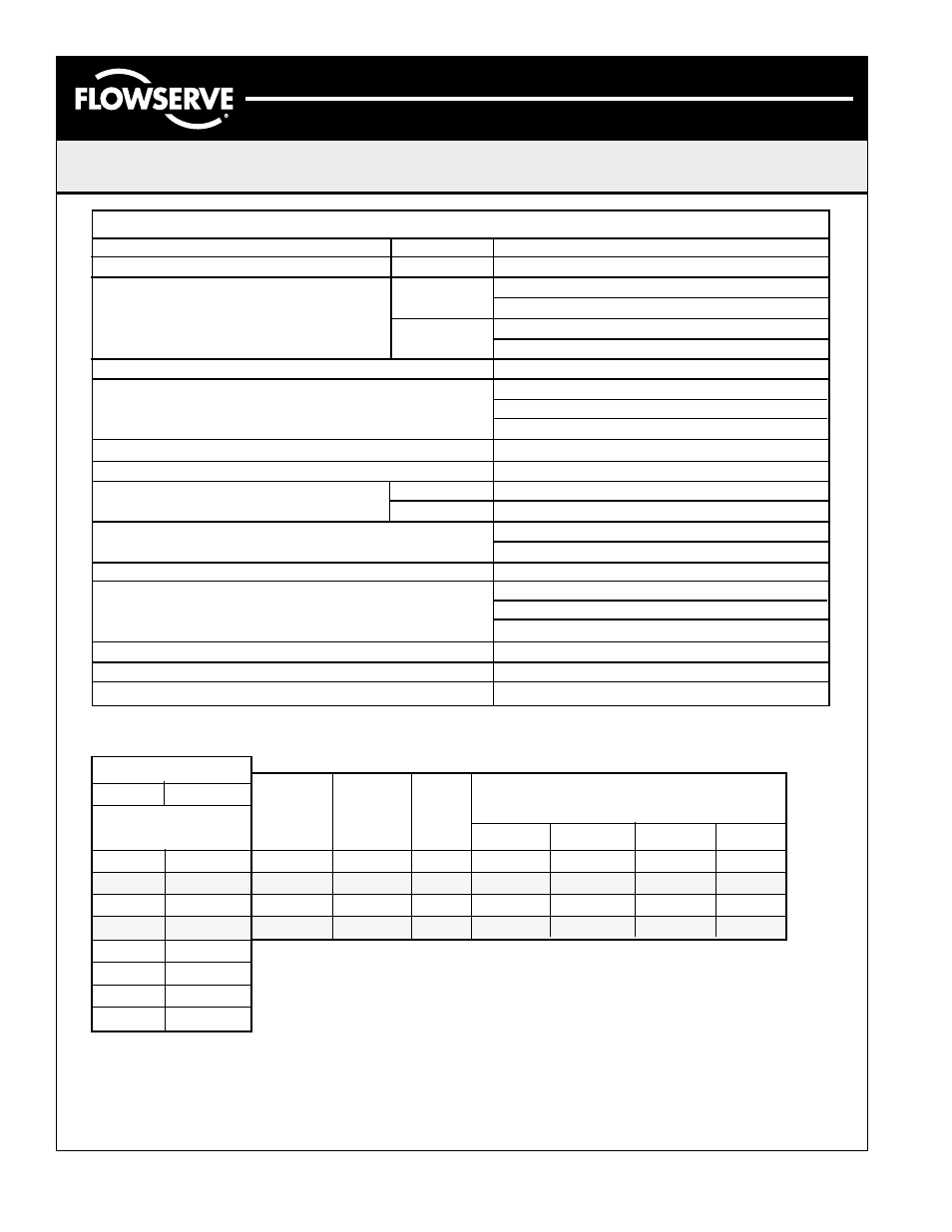
Typical Actuator Specifications
Action
Reversible
Supply Voltages
AC: +/
115VAC (1 Ph)
10%
230VAC (1 Ph)
50/60Hz
24VAC (1 Ph)
DC:
12VDC
24VDC
Temperature Rating
-20
°
F (-28
°
C) to 160
°
F (70
°
C)
Enclosure Ratings / Device Testing
CSA Enclosure 4
NEMA 4, 4X
89/336/EEC Directive for CE Marking
Range of Operation
0
°
to 180
°
AC Motor Thermal Protection
Automatically resetting
Motor Types
AC:
Permanent Split Capacitor
DC:
Brush
Travel and Aux. Switches
SPDT, Form C 15 amp 125 1/2 HP 10 amp
250VAC, 1/2 amp 125 VDC
Conduit Connections
(1) 3/4-14 NPT
Corrosion Protection
Enclosure: Zytel engineered resin
Cover Screws: Stainless Steel
Output Shaft: Dacromet Coating
Terminal Strip Hookup
300V, 30A, 12-26 AWG
Lubrication
Permanently lubricated
Gear Train
Heat treated alloy steel, rated to stall torque
Note: The above ratings may change depending on model configurations and options provided.
Products may differ as the result of the Company policy of continuous product improvement.
Actuator Model
CPL1
CPL2
Cycle Times
Sec/90
°
5
6
3
4
3
4
8
7
100
225
Torque (in-lbs)
11
25
Torque (Nm)
4
5
Weights Lbs (kg.)
CPL1
CPL2
CPL1
CPL2
Std
115
50
0.3
0.5
.04
0.5
B
12
100
1
1.6
*
*
C
24
100
0.5
0.8
*
*
D
230
50
0.11
0.18
0.12
0.2
Opt.
Motor
Desig.
Motor
Voltage
Duty
Cycle
(%)
Run Current
(amp)
Locked Rotor
(amp)
1. Cycle times are approximate under no load conditions and may vary slightly under actual
operating conditions.
2. Duty cycles are rated at 70
°
F. The duty rates may be less under loaded conditions.
3. Do not lock up DC motors.