Troubleshooting – Flowserve CENTURA Analog Output Options Calibration User Manual
Page 2
LME0011-1 (AUTO-68) 12/00
©
2000, Flowserve Corporation, Provo, Utah
3-Position Control/Dribble Control
SR Limit Switch Method
Flowserve Corporation
765 South 100 East
Phone: 801 373 3028
Flow Control Division
Provo, Utah 84606
Facsimile: 801 489 2228
www.flowserve.com
Email: [email protected]
Automax Valve Automation Systems
Installation, Operation and Maintenance Instructions
Page 2 of 2
Problem
Output is not continuous throughout actuator/valve stroke
(experience a band of max. output)
Transmitter does not out 4 or 20 mA at desired end of
travel.
Transmitter module does not provide current signal or
provide constant signal.
Output not linear or does not track valve position/rotation
Probable Cause/Solution
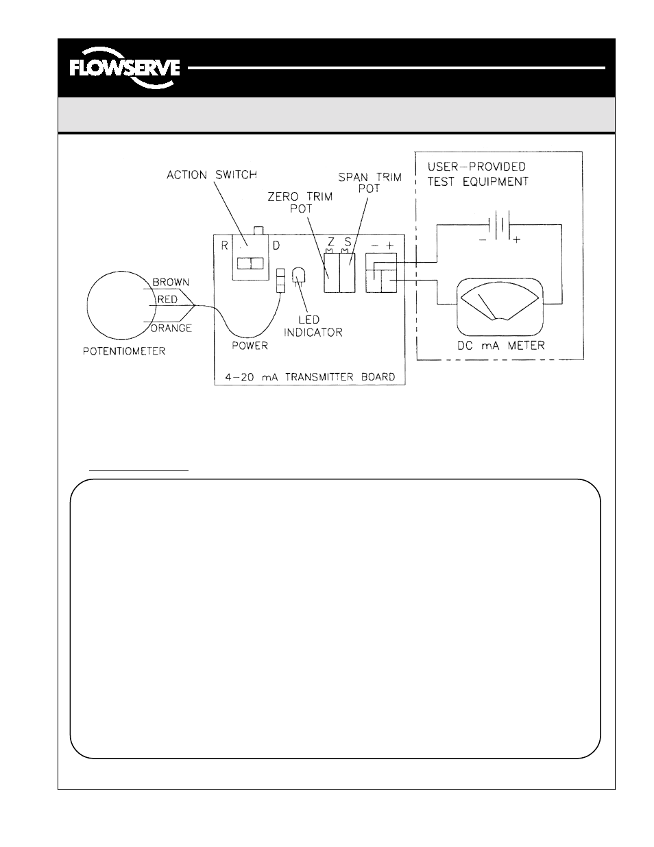
Potentiometer is out of adjustment (see “Resistive
Feedback Calibration” or 4-20mA Current Transmitter
Calibration” steps 2-4).
Zero or span trim potentiometer is out of adjustment (see
4-20mA Current Transmitter Calibration).
Circuit Board LED not lit:
1. Loose or shorted signal connection (no loop power).
2. Controller board not responding (replace board)
Circuit Board LED lit:
1. Potentiometer disengaged.
2. Defective potentiometer or controller board. Replace
defective component.
Input signal not linear. Linkage or drive mechanism is
introducing non-linearity. Zero span trim potentiometer is
out of adjustment (see 4-20mA Current Transmitter
Calibration).
Troubleshooting
Figure 1 – 4-20 mA Transmitter Diagram