Flowserve XL UltraSwitch User Manual
Page 2
© 2004, Flowserve Corporation, Printed in USA
Automax Valve Automation Systems
Installation, Operation and Maintenance Instructions
Flowserve Corporation
1350 N. Mountain Springs Parkway
1978 Foreman Dr.
Flow Control Division
Springville, Utah 84663-3004
Cookeville, TN 38501
www.flowserve.com
Phone: 801 489 8611
Phone: 931 432 4021
FCD AXAIMO0031-00 (LML0005-1) (AUTO-31) 7/04
Page 2 of 2
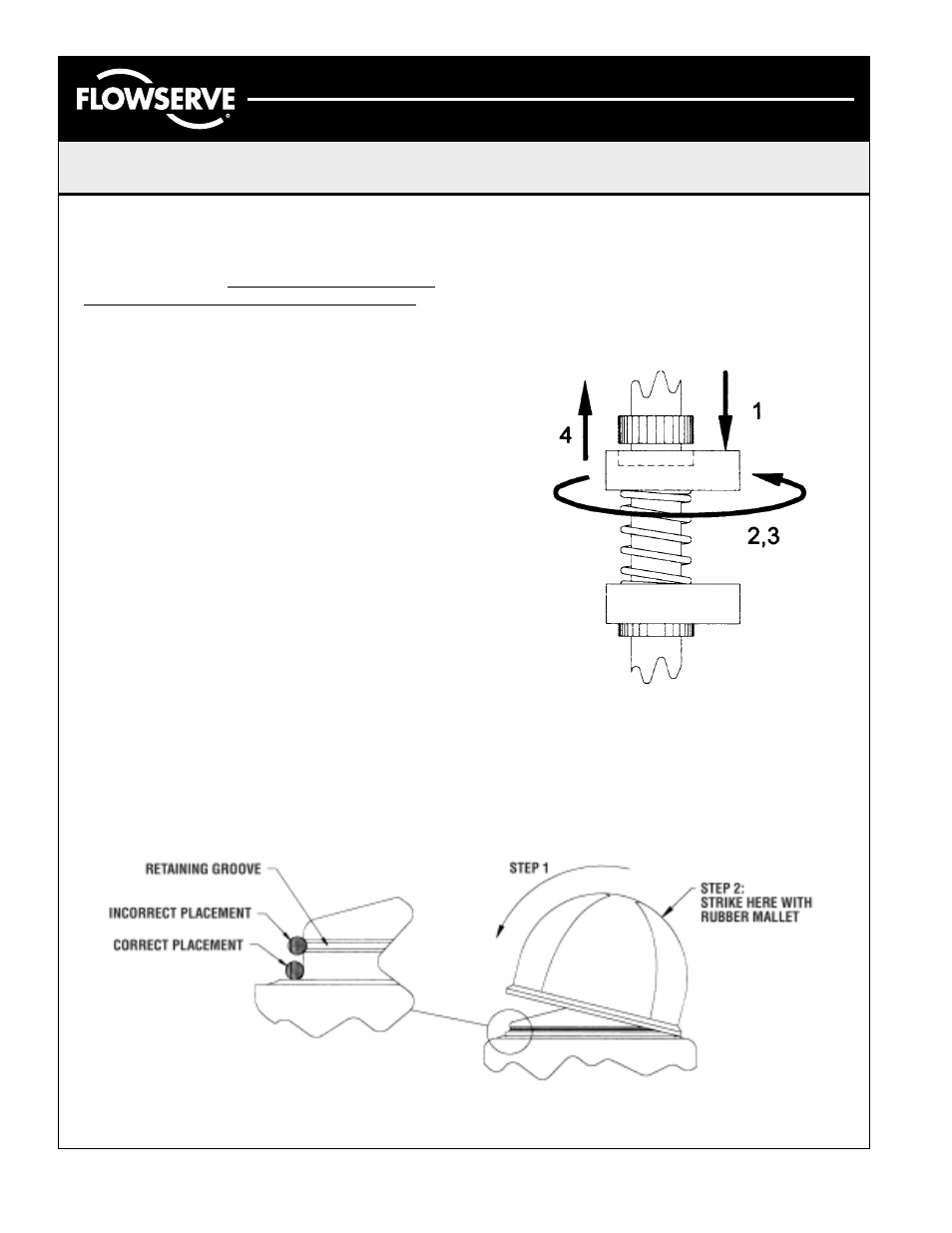
Adjusting Limit Switches
UltraSwitch™ enclosures feature quick-set cams which
are used to trip the limit switches. These cams are easily
adjusted without tools.
Caution: disconnect power before
removing cover when installed in hazardous locations.
Remove cover and set aside. Rotate actuator/valve to full
clockwise (CW) position. Adjust cam(s) associated with CW
as follows:
1.
Push or pull cam against spring to disengage it
from splines.
2.
Rotate cam CW breaking contact with switch
(or moving magnet away from switch).
3.
Continue rotating cam CW just until switch trips.
4.
Release cam and reengage it with splines.
Rotate actuator/valve to full counterclockwise (CCW)
position. Adjust cam(s) associated with CCW as
described in steps 1 through 4, except rotate cam(s) CCW.
Note: factory setting is top switch = CW (closed), second
switch = CCW (open), third switch = CW, and fourth
switch = CCW.
Adjusting Pharos™ Position Indicator
Pharos visual indicators are easily adjusted to match
the dome’s clear windows to the rotor’s red and green
quadrants. Simply pry upward under dome “flange” with a
large, flat-bladed screwdriver to remove. Make sure o-ring
is fully seated against the flat dome sealing surface, not in
the dome retaining groove, as shown. Then install dome in
a tilted fashion, engaging one of the dome locking tabs in
the dome retaining groove. Make sure dome windows line
up with rotor quadrants. Finally, using a rubber mallet,
strike dome as shown to engage all locking tabs.