Worcester controls – Flowserve 10–40 39 ACCESS M Mounted Limit Switch User Manual
Page 3
WCAIM2032
10–40 39 ACCESS M Mounted Limit Switch and Solenoid with AS-Interface
3
4. Assemble the enclosure, with probe assemblies, to the actuator
inserting the housing gasket between the actuator end cap and
the housing. Important! Do not apply any grease to the gasket,
it must be installed dry. Secure with four machine screws. For
all ACCESS M units, four threaded tamper-proof plugs are
installed over the machine screws. Once installed, no attempt
should be made to remove these plugs. If it becomes necessary
to remove enclosure from actuator end cap, consult Flowserve.
Check the probes for freedom of movement by moving them
back and forth slightly.
5. With assembly complete to this point, it is convenient to make
conduit connections and bring wiring through enclosure. The
power supply to the solenoid coil is three watts. Required
amperage is shown below. It should be noted that the
successful use of this device in hazardous, wet, or other
detrimental environments depends on proper conduit
construction techniques.
Voltage
Holding Amps
24 VDC
.13
6. When the switch package is assembled, one of the probes will
make contact with the switch button. Simply press the switch
package until the mounting screws can be engaged. Tighten
mounting screws until bracket is secure.
7. Switches/sensors (if installed) have been factory adjusted, but
should be rechecked after installation. Adjustment is as follows:
a. With actuator mounted in “standard” fail-closed mounting
configuration (see Step 2) and wired per appropriate wiring
diagram, set actuator in the full-closed position, with the
adjustment screw near its loose limit. The orange LED
indicating solenoid coil continuity will be lit. The orange LED
will remain lit as long as there is power to the circuit board
and there is no short circuit or open circuit with the coil.
However, it should be noted that if there is a short circuit or
open circuit with the coil, the orange LED will only turn off
when an attempt is made to energize the coil. This also
applies to the Input 1 (Bit 1) status.
b. Adjust closed position switch or Namur proximity sensor SW-2
(see Wiring Diagram) by tightening the adjustment screw until
red LED turns on. Then tighten adjustment screw one
additional turn.
With air supplied to actuator, energize the solenoid to change
actuator to its full open position. The yellow and orange LEDs
should be lit indicating power to the coil and coil continuity,
respectively. Adjust the open position switch/sensor SW-1 in
the same manner as the closed position switch/sensor until
the green LED turns on. Then tighten adjustment screw one
additional turn. When the solenoid is de-energized, the
actuator will return to its full closed position. The yellow and
green LEDs will turn off indicating that the solenoid is de-
energized and the actuator is no longer in the full open
position and then the red LED will turn on indicating that the
actuator is now in the full closed position.
Flow Control Division
Worcester Controls
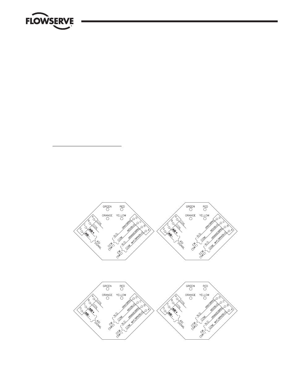
Note: Wire colors in parenthesis are
for proximity sensors only.
For units without
switches/sensors, disregard
switch/sensor wiring, and also
their instructions in section 7.
Fail-Closed
Fail-Closed
(Sizes 10–40 In-line Operation)
(Sizes 10–20 Cross-line,
(Sizes 25–40 Cross-line Operation)
Inverted Operation)
Fail-Open
Fail-Open
(Sizes 10–20 Cross-line Operation,
(Sizes 10–20 In-line,
or with In-line Coupling)
Inverted Operation)
(Sizes 25–40 Cross-line Operation)
LEDs
Red = Closed
Green = Open
Yellow = Solenoid Energized
Orange = Coil Continuity
{