Worcester controls – Flowserve I90 Series Intrinsically Safe Modular Accessory System User Manual
Page 7
3. TROUBLESHOOTING
PROBLEM
POSSIBLE CAUSE(S)
SOLUTION
Shaft binds
Cover not centered
Loosen cover screws and
allow cover to center on
shaft. Retighten cover
screws.
Inadequate lubrication Remove cover and lubricate
shaft hole with bearing
grease, such as Cindol 2321.
If excessive wear or galling is
present, shaft and affected
part of housing will have to
be replaced.
B. SOLENOID BLOCK OPTIONS
The Worcester/McCanna Series I90 Intrinsically Safe M.A.S. can
provide on/off control for both single– and double-acting
pneumatic valve actuators.
Single– or Double-Acting on/off uses one three-way solenoid
valve and one four-way spool valve.
The Intrinsically Safe solenoid valves used in the M.A.S. are
designed to operate on power levels compatible with Intrinsic
Safety requirements. They are Factory Mutual (FM) approved for
Class I, II and III Groups A, B, C, D, E, F and G applications. Entity
Approval #OT4A6.AX (NFPA 493; July 19, 1990).
NOTE 1. For barrier interconnection, refer to maximum barrier
output parameters as referenced on the specific barrier
installation drawing. Connect as follows:
a. V max > Voc of single-channel or Vt of dual-channel barrier.
b. I max > Isc of single-channel or It of dual-channel barrier.
c. Ci + field wiring < Ca of single– or dual-channel barrier.
d. Li + field wiring < La of single– or dual-channel barrier.
For current and wattage values at various input voltages, see table
below.
INPUT VOLTAGE
CURRENT
WATTAGE
15.5 VDC
43 mA
0.7
24 VDC
68 mA
1.63
35 VDC
95 mA
3.3
NOTE 2. Installation of Intrinsically Safe systems is to be done in
accordance with ANSI/ISA R.P. 12.6.
DEFINITIONS
Ca – Maximum Allowed Capacitance
Isc – Maximum Output Current
Voc – Maximum Output Voltage
Ci – Maximum Internal Capacitance
La – Maximum Allowed Inductance
V max – Maximum Input Voltage
I max – Maximum Input Current
Li – Maximum Internal Inductance
Vt – Voltage Total
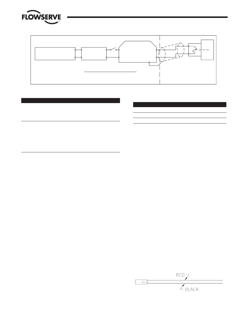
All lead wires are equipped with quick-connect plugs that are
easily connected/disconnected to the solenoid valve. See Figure
11. The plugs will only fit one way — do not force the plugs;
damage can result.
The solenoid block gasket has been designed to adapt the
solenoid blocks to the Series 90 M.A.S. housing air connections.
The gasket is illustrated in Figure 12 for future reference in these
instructions.
AIR SUPPLY: Lubricated or dry air (or other non-corrosive gas).
PRESSURE: 45 – 100 PSI.
FILTRATION: 5 micron strongly recommended.
Flow Control Division
Worcester Controls
WCAIM2033
Intrinsically Safe Modular Accessory System (Series I90)
7
Li = 0
Ci = 0
V max. = 35 V
CHANNEL BARRIER
DUAL OR SINGLE
I max. = 300 mA
MAX. PARAMETERS FOR I.S. VALVE:
HAZARDOUS AREA
SWITCH
POWER SUPPLY
24 VDC NOM.
V nom. = 15.5 V
I nom. = 43 mA
R nom. = 360 Ohm
COIL SPECIFICATIONS:
EXCESS OF 250 VOLTS
OR GENERATE IN
EQUIPMENT CANNOT USE
NON-HAZARDOUS AREA
CIRCUIT (SEE NOTE 1)
TYPICAL INTRINSICALLY SAFE CIRCUIT
Figure 11