Assembly, Worcester controls – Flowserve 90 Series Limit Switch Kit User Manual
Page 2
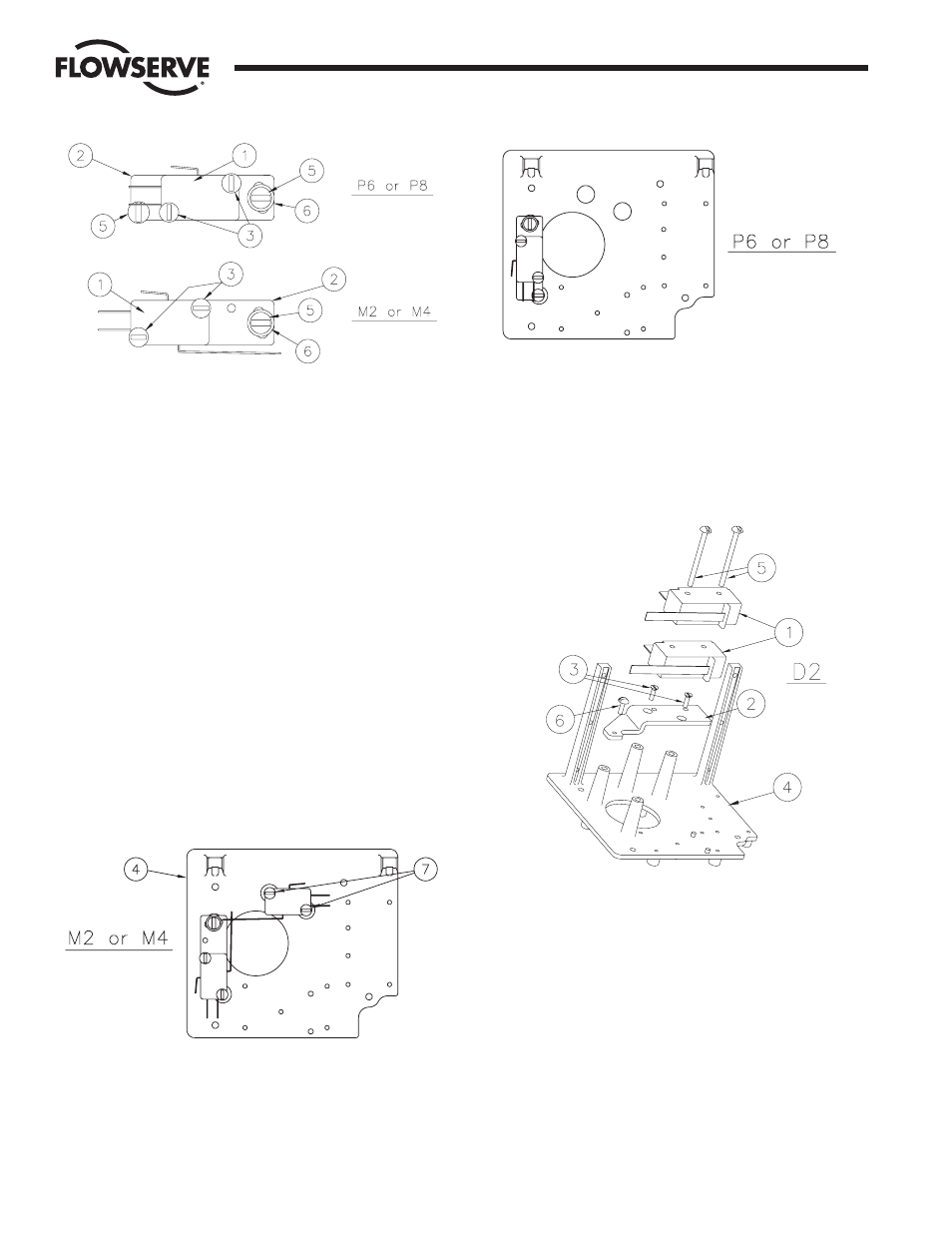
1. ASSEMBLY
a. M2 – TWO SPDT MECHANICAL SWITCHES
M4 – FOUR SPDT MECHANICAL SWITCHES
P6 – TWO AC PROXIMITY SWITCHES
P8 – TWO DC PROXIMITY SWITCHES
1. STACK two switches (item 1) and attach to the adjustment
plate (item 2), as shown above, using two #4-40 x 1" screws
(item 3) provided.
Note: M2, M4 only – One of the screws will thread into a
tapped hole in the adjustment plate while the other engages a
clearance hole without threads.
2. For M2, M4 only – Assemble the switches and adjustment
plate to the baseplate (item 4), as shown below, using the
“loose” #4-40 x 1" screw and the #4-40 x
3
/
8
" screw (item 5)
and #4 washer (item 6). For P6, P8: Assemble the switches to
the baseplate using the two #4-40 x
3
/
8
" screws and the #4
washer. Move the adjustment plate to a middle position and
tighten the screws.
3. FOR M4 ONLY: Stack the other two switches and assemble to
the baseplate using the remaining two #4-40 x 1" screws
(item 7).
b. D2 - TWO DPDT MECHANICAL SWITCHES
1. Attach the mounting plate (item 2) to the baseplate (item 4) in
the location shown using the two #4-40 x
3
/
8
" flat head screws
(item 3) and the one #4-40 x
3
/
8
" round head screw (item 6).
2. Assemble the switches (item 1) to the mounting plate with the
two #6-32 screws (item 5).
Flow Control Division
Worcester Controls
2
Limit Switch Kit for Series 90 Modular Accessory System
WCAIM2044