Flowserve F39 Series Pneumatic Actuator User Manual
Page 11
11
®
Series F39 Pneumatic Actuator - WCENIM2036-00 05/15
For Rev. R3 through R7, sizes 25 through 42 actuators,
replace anti-ejection ring (15J) in its groove on the shaft
(2B), if removed.
For Rev. R2 Models:
• Locate the shaft O-Rings into the actuator body. O-ring
(15D) is the top O-ring while (15E) is the bottom O-Ring.
• Replace the top bearing (15G) and bottom bearing
(15H).
• If the anti-ejection ring (15J) was removed, replace
it in its groove on the shaft (2B). Check that the ring is
properly seated in its groove.
• Replace the shaft in the body through the larger opening
in the bottom of the actuator body.
12.2.6 Replace the stainless steel washer over the top shaft
extension.
12.2.7 For sizes 10–50, very carefully align the piston guide rod
assemblies inside the body. Keep the pistons square to
the body. (This is very important in the 30 F39 actuator
where steel set screws can cause internal body damage if
the piston assemblies “cock” inside the actuator body.)
IMPORTANT:
One piston guide rod assembly has a through
hole drilled in it. It can be easily located by looking down
the ends of both guide rods. This piston assembly must
be reassembled, with its respective guide rod, opposite
the nameplate on the body, as it was removed.
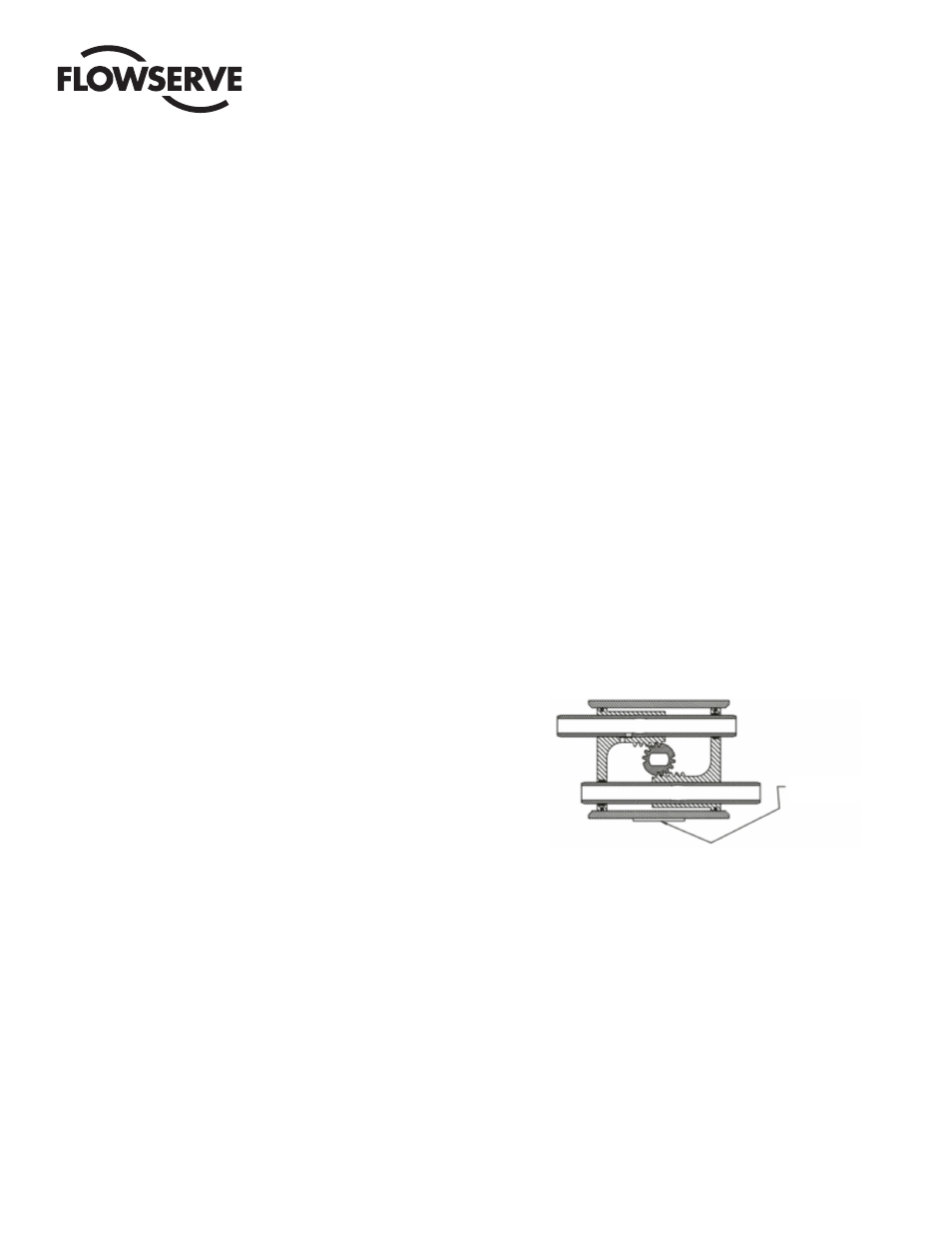
IMPORTANT: Note the relative location of the shaft teeth
and the piston assembly's rack teeth. The above figure is
viewed when looking at the top of the actuator.
For size 05, align the pistons inside the body. Keep the
pistons square to the body.
12.2.8 Align the shaft so that the teeth on the shaft will “pick-
up” the piston assembly’s rack teeth when turning the top
extension of the shaft clockwise (CW). (See Figure 1.)
IMPORTANT: Proper 90°rotation can only be ensured if
the shaft teeth begin to mesh with the piston assembly’s
teeth at the “proper tooth” between these meshing gear
pairs. (See Figure 1.)
12.2 Actuator reassembly
12.2.1 Be sure the actuator surfaces are clean and free of grit
and scratches. If the inside walls of the body are scored,
or the guide rod surfaces are scratched, the actuator will
leak after rebuilding. New parts should be obtained from
the factory. Light tracking, barely detectable to touch, is
acceptable.
12.2.2 All rebuilding kit O-Rings and bearings may now be
installed. Lubricate the standard actuator thoroughly with
a #1 grease. Apply a light film of grease to all O-Rings.
12.2.3 If converting over to a “high-temperature” actuator, or
rebuilding an existing one, lubricate thoroughly with Dow
Corning #7 or other equivalent high temperature silicone
or graphite base grease.
12.2.4 Some Rev. R2 actuators, sizes 10–35, use flanged bear-
ings in the end caps. They resemble a “top hat” (6C), and
are installed with the brim of the hat facing out, and are
retained by “star washers” (16). These bearings and star
washers should not be removed for O-Ring seal replace-
ment. On sizes 10 and 15 only, there is one star washer,
or retainer, per bearing. On sizes 20–35, there are two
star washers per bearing. They are installed one on top
of the other, with the “points” of the “star” overlapping
each other (as opposed to being on top of each other). All
the washers must be pressed in firmly and straight. The
points of the star are bent slightly. When installed, they
bear back, away from the hole.
For sizes 10–50 Rev. R2 and 10–42 Rev. R3 through R7
actuators, replace the two split-ring style bearings (6A)
and one guide rod O-ring (15B) in each end cap.
Replace the split-ring style bearing (6B) and guide rod
O-ring(s) (15B) into I.D. groove(s) in each piston (3).
Install O-Rings (15C) onto pistons.
For size 05 actuators, install O-rings (15C) onto the
pistons.
12.2.5 Replace O-ring (15E) and bearing (15H) (10–42 sizes
only) on the bottom of shaft. On the top of the shaft add
the two stainless steel washers (10–35 sizes only) with
the thrust bearing (10) between them. NOTE: For sizes
40 and 42 Rev. R3 through R6 and sizes 10 to 50 Rev.
R7, only a single stainless steel washer is used and thrust
bearing (10) is not used. Locate the top bearing (15G)
and O-ring (15D) into the body. NOTE: For sizes 10–35
Rev. R7 and size 05 actuators, top bearing (15G) is flat
and the same as, and interchangeable with, thrust bearing
(10). Insert the shaft through the larger opening in the
bottom of the body.
°
Nameplate
Figure 1
Pistons at End of Body