Flowserve APEX 4000 Pneumatic Positioner User Manual
Page 2
© 2003, Flowserve Corporation, Printed in USA
AXAIMO36-00 (AUTO-112)
7/03
3-Position Control/Dribble Control
SR Limit Switch Method
Automax Valve Automation Systems
Installation, Operation and Maintenance Instructions
Flowserve Corporation
1350 N. Mountain Springs Parkway
1978 Foreman Dr.
Flow Control Division
Springville, Utah 84663-3004
Cookeville, TN 38501
www.flowserve.com
Phone: 801 489 8611
Phone: 931 432 4021
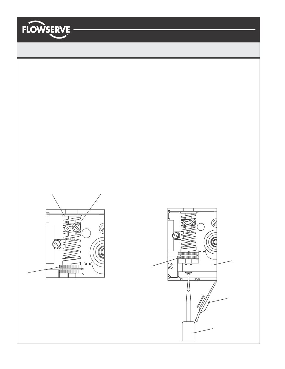
Calibration:
The unit is shipped from the factory pre-calibrated for 90
degree travel (
±0.5 degrees rotation - can also be 30/45/
60 degrees, see installed cam). For most applications,
the valve closed position is much more critical than the
valve open position. Most attention should be made to
the valve closed position. Always start calibration
procedure by applying 0% input signal, then adjusting
zero position. The positioner is calibrated by turning
thumbwheels (1) and (4). Arrows on arm (5) indicate
turning direction of thumbwheels.
"+" = increase zero/span
"-" = decrease zero/span
Caution:
Cam pinch points may injure fingers. Be sure to
avoid placing fingers and other objects in cam pinch
points. Also avoid touching balance beam and spool
while making adjustments as unpredictable cam rotation
may result. Finally, maintain control of input signal while
making adjustments.
Page 2 of 8
Calibration Procedure:
1.
Apply O% input signal (0% = 20 kPa, 3 psi, or 4 mA).
2.
Wait for steady state. It is important to wait for steady
state. On very large actuators, it can take minutes to
establish.
3.
Adjust zero by turning the silver (lower) thumbwheel (4)
with finger or with screwdriver (7) from the outside.
4.
Apply 100% input signal (100% = 100 kPa, 15 psi, or
20 mA).
5.
Wait for steady state; remember result.
6.
Apply 0% input signal.
7.
Adjust span per result in step (5) above. This is
accomplished by first loosening screw (2), then turning
the yellow (upper) thumbwheel (1) in appropriate
direction with finger. Tighten screw 2. Spring top must
not be in contact with spring guide (3).
8.
Check and adjust zero.
9.
Repeat steps 2 through 8 until desired calibration is
achieved.
▲
▼
2
3
1
Span Adjustment
--
SPAN
+
+
5
6
7
4
Zero
Adjustment
ZERO
+
+
SPAN
--
--
+
+