Disassembly, Reversing spring action, Maintenance – Flowserve Handwheels and Limit Stop User Manual
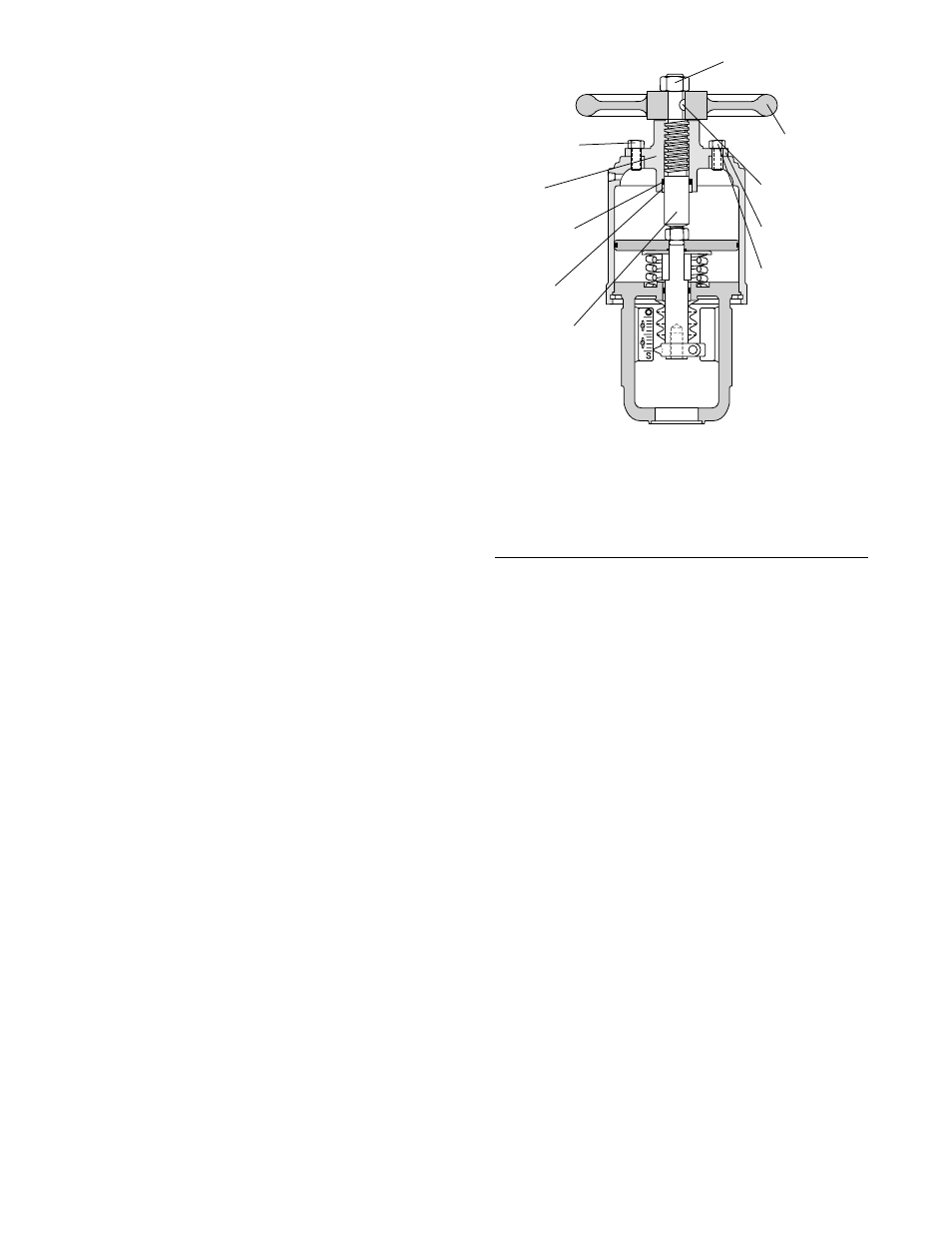
Page 8: Figure 4: top-mounted, push-only handwheel
5-8
Flowserve Corporation, Valtek Control Products, Tel. USA 801 489 8611
maintain a coat of multi-purpose lubricant on the screw
at all times. To do this:
1. Turn the handwheel counter-clockwise until the
handwheel runs out of threads and stops, exposing
the full length of the screw.
2. Clean and lubricate the exposed threads.
Disassembly
Refer to Figure 4:
1. The handwheel assembly can be disassembled
while mounted on the valve, or the actuator can be
removed and disassembled separately (see the
valve’s maintenance bulletins for instructions).
WARNING: Repressurize line and actuator to
atmospheric pressure before removing the ac-
tuator from the valve, or serious personal injury
could result.
2. Rotate the handwheel counter-clockwise until the
handwheel runs out of threads and stops (neutral
position). This releases some of the spring com-
pression.
WARNING: Cylinder is spring loaded. Do not
attempt to remove flange bolts without follow-
ing Steps 3 and 4 exactly or serious injury can
occur.
3. Remove four of the six handwheel flange bolts,
leaving two opposing bolts.
4. Remove two remaining handwheel flange bolts
17. Screw on handwheel cap until no movement can be
felt in the cap liner.
18. Tighten handwheel cap assembly.
CAUTION: Excessive tightening is not required.
This is not a pressure retaining seal.
Reversing Spring Action
After following the disassembly of the actuator as
outlined, the spring action can be reversed as follows:
1. Remove cylinder retaining ring, cylinder and spring.
2. Drive out the stem pin locking the handwheel stem
to the actuator stem.
3. Screw the handwheel stem off the actuator stem.
Make sure a wrench is used to prevent the actuator
stem from rotating.
CAUTION: Damage to the seating surfaces of
the plug and seat can result if the plug is allowed
to rotate during removal of the handwheel stem.
4. Reinstall the actuator spacer on the opposite side of
the piston. Replace the piston stem O-ring during
this step.
5. Screw the handwheel stem back into the actuator
stem. Realign stem pin hole and reinsert stem pin.
6. Reassemble actuator with spring under the piston
for air-to-open (spring-to-retract). The spring should
be installed over the piston for air-to-close (spring-
to-extend). Make sure the actuator spacer is on the
same side of the piston as the spring.
7. Reassemble by following the instructions in the
'Reassembly' section.
NOTE: The spring button and spring button guide
are not used in the air-to-open configuration and
should be removed and set aside. When changing
to the air-to-close configuration, a spring button and
spring button guide must be obtained from Flowserve
or from existing supply.
TOP-MOUNTED, PUSH-ONLY
HANDWHEELS (Rotary Actuators Only)
Operation
The push-only handwheel can be used to close the
valve or as a limit stop to limit valve opening:
1. If provided, set the three-way bypass valve on
'manual' to vent air pressure to the actuator.
2. Turn handwheel in a clockwise direction to extend
the actuator stem and to lower the valve plug.
3. To return the valve to automatic control, turn the
handwheel counter-clockwise until the handwheel
runs out of threads and stops (neutral position), and
set the three-way valve on 'auto.'
4. To limit the opening of the valve, move the hand-
wheel from neutral to the desired limiting position.
Maintenance
For proper operation of the handwheel, it is important to
Figure 4: Top-mounted,
Push-only Handwheel
NOTE: Item numbers shown above correspond directly to the
valve’s bill of material. Refer to the bill of material for specific part
numbers.
Handwheel Stem Nut
(Item No. 348)
Handwheel
(Item No. 393)
Handwheel Key
(Item No. 370)
Flange Gasket
(Item No. 378)
Flange Bolt
(Item No. 333)
Bolt Gasket
(Item No. 379)
Flange
(Item No. 389)
Handwheel
Stem O-ring
(Item No. 276)
Bushing
(Item No. 390)
Handwheel
Stem
(Item No. 380)