Flowserve 75 Actuator DC Motor Leads User Manual
Ferrite beads, 75 actuator dc motor leads, Installation, operation and maintenance
Parts Included in Ferrite Bead Kit
Description
Quantity
Tubular Ferrite Beads
4
Lead Wire – Red
1
Lead Wire – Black
1
Wire Ties
3
Crimp-On Terminals
2
1. Begin by turning off the power and removing the cover.
2. Remove the motor leads from the front of terminals 3 and 4,
making a note of which color motor lead goes where. Pull the
motor leads free, back toward the motor(s).
3. Using the tubular ferrite beads, install a ferrite bead on each red
and each black motor lead as close to the motor(s) as pos-
sible. Each motor lead should pass through its ferrite bead a
minimum of three times.
4. Route the motor leads back to the front of terminals 3 and 4. If
necessary, extend the motor leads with extra red and black wire
pigtails (using the supplied pigtails and crimp-on terminals in
the kit) to make the motor leads reach the front of terminals 3
and 4 if they are now too short. Take appropriate precautions
to ensure that the junction of the extra wires with the existing
motor leads is properly crimped. If there are two motors, crimp
the two red motor leads together with the red pigtail and then
run the single red lead back to the front of the actuator. Do the
same with the two black motor leads and black pigtail.
5. Reconnect the motor leads to the front of terminals 3 and 4,
ensuring that the appropriate color is returned to each terminal.
6. Replace the cover and restore power to the unit.
FCD WCAIM2073-00 (Part 19252)
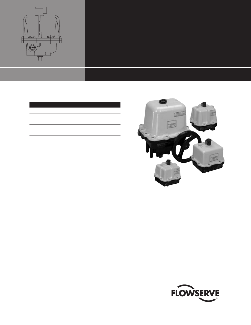
Ferrite Beads
75 Actuator DC Motor Leads
Installation, Operation and Maintenance
���������������������������