Wiring, Internal wiring, External wiring – Flowserve 4-75 Position Indicator User Manual
Page 2: Worcester actuation systems, Flow control
Flow Control
Worcester Actuation Systems
2
4-75 Position Indicator
FCD WCAIM2070-00
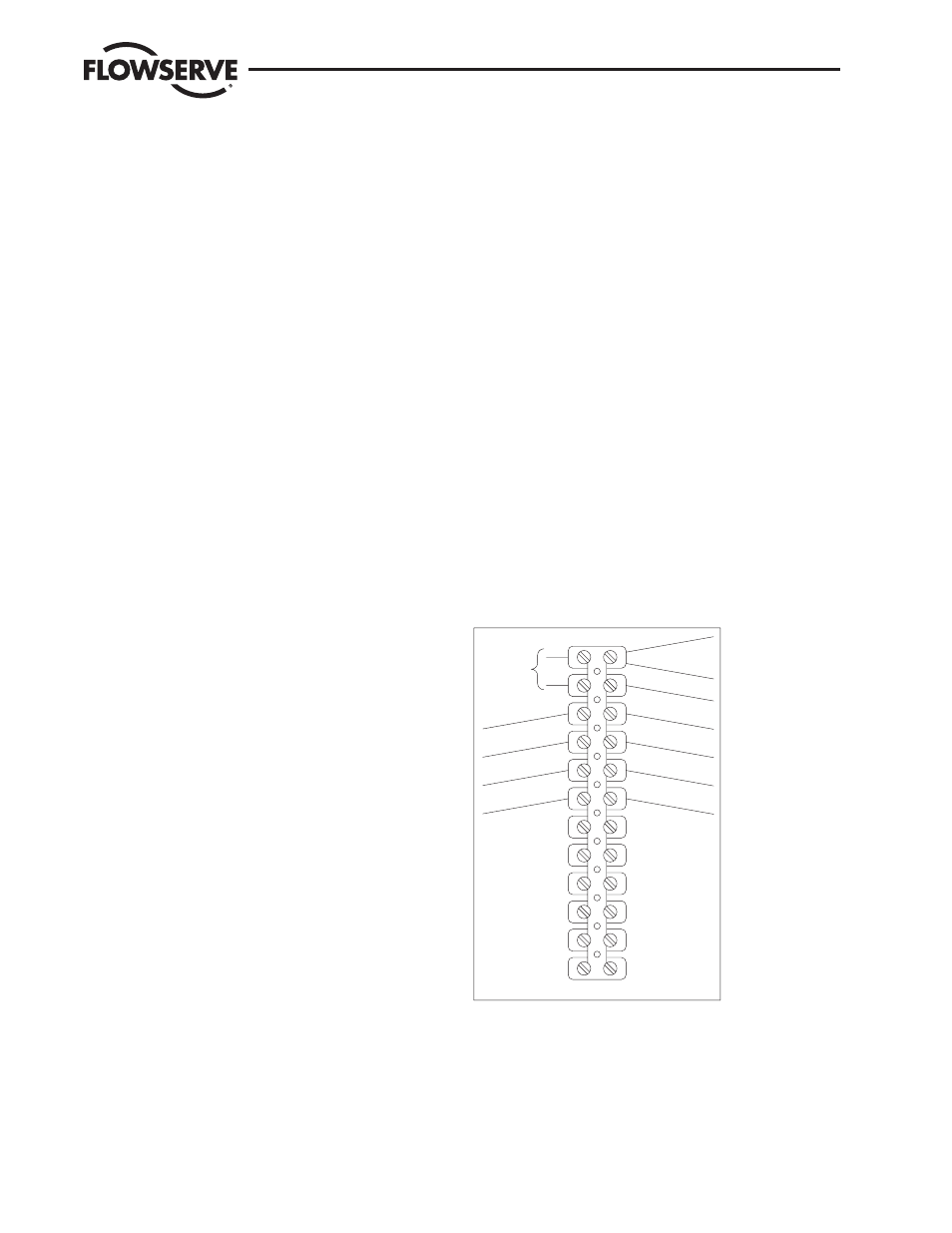
3. Wiring
(See Figure 2.)
NOTES: All wiring to terminal strip should be inserted only to mid-
point of terminal strip.
When there are multiple wires going to terminal 1, use the short
white wire included in kit. Connect it to terminal 1 and then
splice it to the other white wires (common) using the closed end
splice provided.
Internal Wiring
There is internal wiring between the actuator terminal strip, feedback
potentiometer, and position indicator PC board. The white wire
(common) from PC board is wired to terminal 1 on internal side; the
brown wire (hot) from PC board is wired to terminal 2 on internal
side. Connect feedback potentiometer wires to the 4-75 position
indicator board terminal block (green to terminal 3, white/black to
terminal 2, and purple to terminal 1).
Remove yellow wire from terminal 5 and brown wire from terminal
6, disconnect them from N.O. contacts of switches 1 and 2 and
discard them. Output signal from PC board red wire (+) is wired to
terminal 5 and black wire (-) is wired to terminal 6 on internal strip
of terminal strip.
NOTE: Attach wiring diagram label, included with kit, on inside of
cover, or modify existing label for the 4-75 option by marking termi-
nal 5 “+”, terminal 6 “-”, and adding “4-20 mA output.”
For actuator using a 4-75 Position Indicator with a DFC17 Control-
ler, the red and black wires from the indicator board will have to be
spliced directly to the external positive and negative output (Meter)
wires, respectively.
NOTE: Prior to wiring, follow Position Indicator board output cali-
bration instructions in Section 4.
External Wiring
External wiring is between actuator terminal strip and outside power
supply and various controls. Common wire of the power supply is
wired to terminal 1 and hot wire of the power supply to terminal 2.
The actuator motor windings are electrically powered through its
own individual external single pole, double throw switch (supplied
by customer); counterclockwise and/or “to open” wire is wired to
terminal 3; clockwise and/or “to close” wire is wired to terminal
4, as shown in wiring diagram for actuator. An outside position
indicator meter is wired with positive connection to terminal 5 and
negative connection to terminal 6.
NOTE: External switch not needed when position indicator is
used with DFC17 controller, as controller board will power
motor windings.
Securely tighten all terminal screws. Secure all wires neatly with the
cable ties (9). Keep wiring away from all rotating parts and ensure
wiring is not pinched when actuator cover is installed.
Grounding wires should be connected to green-colored grounding
screw (if present) on actuator base or to any base plate mounting
screw in actuator.
Figure 2—Wiring of 4-75 120 VAC Position Indicator
12
11
9
8
7
10
EXTERNAL
INTERNAL
BOAR
D
6
POSITIVE
NEGATIVE
5
4
3
2
1
NEUT.
HOT
4-20 mA—OUTPUT
FROM EXT
. SWITCH
FROM EXT
. SWITCH
CLOSE—CW WIRE
4-20 mA—OUTPUT
VAC POWER
TO BOARD
OPEN—CCW WIRE
RED—MOTOR
BLACK—MOTO
R
BLACK—CIRCUI
T
BROWN—CIRCUIT BOAR
D
HOT
WHITE—CIRCUIT BOARD
COMMON
WHITE MOT
. COMMON(S
)
CCW LIMIT SW
CW LIMIT
SW
RED—CIRCUI
T
BOA
RD