Automax buswitch, Profibus-dp – Flowserve BUSwitch-Profibus-DP User Manual
Page 3
LML0012-0 8/99
Page 3 of 6
©1999, Flowserve Corporation, Provo, Utah
Flowserve Corporation
Flow Control Division
Automax BUSwitch
TM
– Profibus-DP
765 South 100 East
Provo, Utah 84606
www.flowserve.com
Phone: 801 373 3028
Facsimile: 801 489 2228
Email: [email protected]
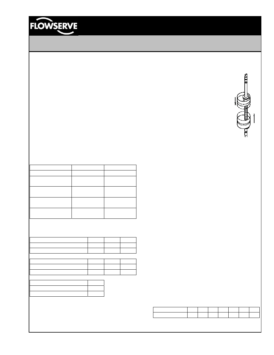
Figure 4
Special notes on the fieldbus cabling.
Due to the high-speed communication capability of
Profibus-DP networks, it is important to follow
established specifications closely to ensure full
communication capability. Governance of the
physical level requirements is specified in the
European Norm EN50170: "General Purpose Field
Communication System.” To obtain the maximum
communication capability it is highly recommended
to only use type ‘A’ cable as defined in table one
below. As a rule, data speed and maximum
segment length are inversely related. At 9.6 kBaud,
segment lengths up to 1200 meters are allowed. At
12 MBaud the segment length falls to 100 meters.
The following tables were obtained from The Rapid
Way to Profibus-DP by Manfred Popp; available
from the PROFIBUS Nutzerorganisation (PNO) as
order number 4.072. To order, contact the Profibus
Trade Organization (PTO) in your area.
Line Parameters
Line Type A
Line Type B
Impedance (
Ω)
135 to 165
100 to 130
Capacitance per
unit length (pF/m)
<30 <60
Loop resistance
(
Ω/km)
110 ---
Core diameter
(mm)
0.64 >0.53
Core cross
section (mm
2
)
>0.34 >0.22
Table 1
Recommended Line Lengths
Transmission rate (kBaud)
9.6
19.2 93.75
Line Type A
1200 1200 1200
Line Type B
1200 1200 1200
Transmission rate (kBaud) 187.5
500
1500
Line Type A
1000
400
200
Line Type B
600
200
-
Transmission rate (kBaud) 1200
Line Type A
100
Line Type B
-
Table 2
Adjustment of Switch Cams
1. Loosen five captive cover screws and remove
lid, turning slightly while lifting.
2. Place the actuator in the clock-wise (CW)
position and apply 24 VDC to the Profibus-DP
Interface Card.
3. Push down on the top cam (figure 4)
until it clears the splined coupler and
rotate clockwise until the CW LED (red)
is illuminated.
4. Release the cam and insure that it
fully engages the spline.
5. Place the actuator in the counter-
clockwise (CCW) position.
6. Pull up on the lower cam (figure 4)
until it clears its splined coupler and
rotate counter-clockwise until the
CCW LED (green) is illuminated.
7. Release the cam and insure that
it fully engages the spline.
8. Cycle the actuator to insure that
each LED is illuminated at the appropriate time.
Some minor readjustment might be necessary.
9. Clean base, lid flanges, and replace lid on base.
Make sure wires are NOT caught between
flanges, and tighten captive screws.
BUSwitch Configuration
Configuration of the BUSwitch is accomplished
through three main steps; physically connecting to
the network, setting the device address / operating
mode and sending operating parameters over the
Profibus segment. The physical connection to the
segment was covered previously in this document.
Setting of the device address and operating mode is
accomplished by a printed circuit board (PCB)
mounted switch assembly (refer to figure three).
The switch assembly has eight numbered positions,
each of which can be set to either ON or OFF.
Switch #1 sets dual coil operation when in the ON
position, or single coil operation when placed in the
OFF position. Switches 2 through 8 are used to set
the address of the BUSwitch on the Profibus
segment. The switches are a binary representation
of the address with switch number 2 being the most
significant digit and switch number 8 being the least
significant digit. The decimal value of each switch
when set to the ON position is as follows.
Switch
#
2 3 4 5 6 7 8
Decimal
Value 64 32 16 8 4 2 1
Table 3