Service problems, Edward valves, Cont.) – Flowserve Edward Cast Steel Bolted Bonnet Valves User Manual
Page 4: Important, Bonnet gasket leak, Table a
4
Flow Control Division
Edward Valves
Service Problems
(cont.)
enough to prevent leakage but not enough
to develop excessive operating torque.
When the gland has advanced approxi-
mately half way into the packing chamber,
it in recommended that additional packing
rings be added. To obtain best results,the
stem should be thoroughly cleaned.
Replacement packing should be the same
as that originally furnished.
We recommend that replacement packing
be purchased from Edward Valves, to
assure packing with the proper density
and corrosion inhibitors is always used.
IMPORTANT:
Long service life from modern graphitic
packing requires that adequate preloads
be applied when repacking.
1. All parts should be clean and not
scored or pitted, especially the stem.
2. The valve internal parts and bonnet
should be assembled prior to
installing the packing.
3. Position split packing rings with the
ends of adjacent rings rotated 90°.
4. Install in the following sequence:
Bottom Ring
–
Braided Ring
Center Rings –
Die formed
expanded graphite
Top Ring
–
Braided Ring
5. Clean and lubricate the gland eye-
bolts.
6. Carefully seat each individual pack-
ing ring before adding the next ring.
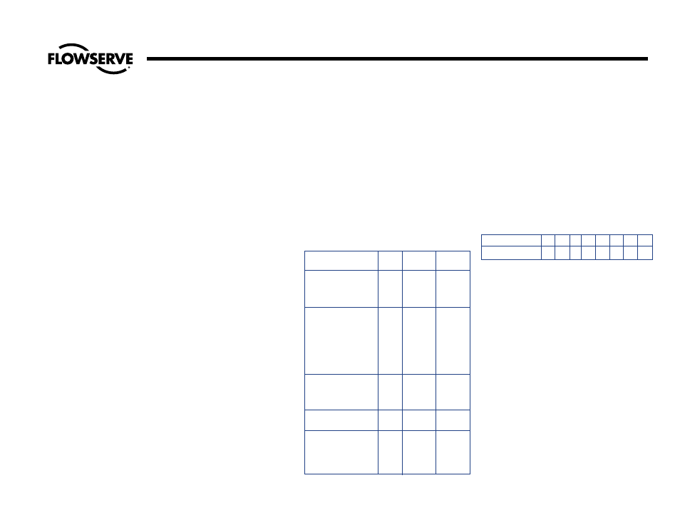
7. Apply the recommended torque to
the gland nuts evenly without cocking
the gland. See Table A for recom-
mended torques.
8. Tighten the nuts to the initial values
shown, then loosen and re-tighten to
the final torque.
9. Stroke the valve, then re-check the
gland nut torques.
BONNET GASKET LEAK
A torque wrench should be used for tight-
ening the bonnet or cover retainer studs or
cap screws which are used to preload the
soft iron gasket.
The following procedure is recommended:
1. Guard against leakage by having these
bolts tight at all times.
2. With line pressure in the valve, all nuts
or cap screws should be tightened to
the torque shown below.
Should the leak fail to stop after tightening,
it must be concluded that there is an imper-
fect seal, and the valve will have to be
opened for examination. Such a leak may
result from either of the following causes:
1. Incomplete Seal Between Bonnet and
Gasket or Body and Gasket. An incom-
plete seal around the gasket seating sur-
faces may be caused by corrosion, dirt,
chips, or other foreign matter on the
mating surfaces. An incomplete seal
may be caused by surface imperfections
in the body or bonnet surfaces in the
form of pin holes, extended cracks, or
indentations where the metal has failed
sometime after valve installation and
use. Such imperfections may be surface
indications of deeper flaws in the body
casting which may cause a by-pass
around the gasket.
INITIAL
FINAL
FIGURE NUMBERS
SIZE TORQUE TORQUE
328, 328Y,
329, 329Y,
2.5
24
6
1441, 1441Y,
1443, 1443Y
302, 302Y
2.5
24
6
303, 303Y
3
27
6
304, 304Y
4
27
6
318, 318Y
5
41
9
319, 319Y
6
55
13
8
60
14
10
89
21
12
143
33
1302, 1302Y
6
40
9
1314, 1314Y
8
68
16
1324, 1324Y
10
76
18
12
140
32
1641, 1641Y
2.5
24
7
1643, 1643Y
604, 604Y
2.5
27
8
605, 605Y
3
27
8
618, 618Y
4
41
12
619, 619Y
5
55
16
6
60
17
TABLE A
GLAND BOLT TORQUES, FT-LBS
Bolt diameter, Inches
1/2 9/16 5/8 3/4
7/8
1
1-1/8 1-1/4
Torque, Ft. Lbs.
45 68 90 150 240 370 585 750