Kammer control valves – Flowserve 025000 Series User Manual
Page 9
9
Flow Control Division
Kammer Control Valves
11.00
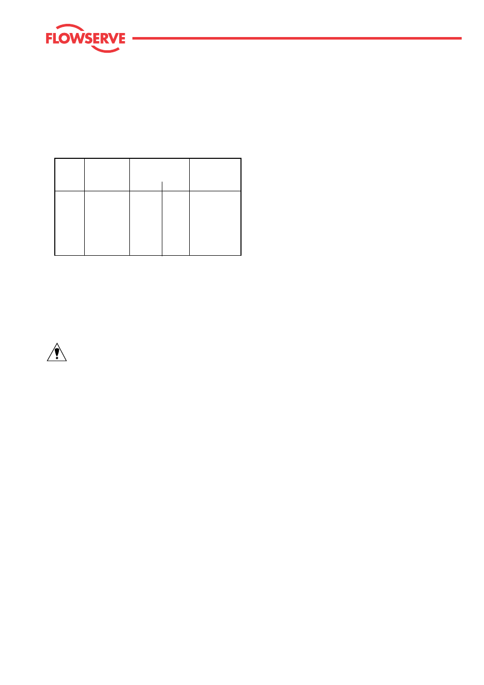
Hex bolt
Waisted bolt
Studs
Thread
DIN 933
DIN 2510
DIN 939
A2-70
1.7709
1.7258
CK 35
M 8
20 Nm
–
–
–
M 10
35 Nm
–
–
20 Nm
M 12
60 Nm
44 Nm 36 Nm
35 Nm
M 16
145 Nm
115 Nm 92 Nm
80 Nm
M 20
280 Nm
–
–
–
M 24
250 Nm
–
–
270 Nm
4.2.11 Using torque wrench, gradually tighten all bolts alter-
nating crosswise to following torques (see following
table).
Note: When the housing bolts are tightened, the halves
of the housing must always be parallel (see fig. 5).
4.2.12 Replace packing by inserting packing rings one at a
time tapping each one down with a suitable bushing.
IMPORTANT: ensure that the gaps in the packing
rings are distibuted evenly around the circumferance
in the packing box (gaps not in line).
Note:
different packings and fitting sequence is shown
in the spare parts list.
6.1.13 Insert packing follower. Fit gland nut for transport
purposes only. Gland nut to be fitted correctly and
tightened down when actuator is mounted.
4.2.14 When performing subsequent pressure test, note the
max. permissible pressure for the bellows. After the
check for leaks, close off test connection with plug or
suitable gauge.