Flowserve NAF-Check Non Return Check Valves User Manual
Page 3
Version
Designation
Item no.
NAF specification
DIN equivalent
DN 40 + 50
1
SS 2343 (=
^
ASTM, A 276 316) X5CrNiNb 18 14 3
1.4436
5
)
Body
DN 65-250
ASTM A 351 CF8M
X10CrNiMo 18 10
1.4581
DN 300-1000
ASTM A 216 WCC
GP 240 GH (GS-C 25)
1.0619
Steel
Disc
DN 40 + 50
2
SS 2395 –
X2CrNiMoN 17 13 5
1.4439
DN 65-1000
SS 2387 –
X4CrNiMo 16 5
1.4418
5
)
Hinge
3
SS 2303 (=
^
ASTM, A 276 420) X20Cr 13
1.4021
Spring
DN 65-1000
4
SS 2388 –
X7CrNiAl 17 7
1.4568
Body
DN 40 + 50
1
SS 2343 (=
^
ASTM, A 276 316) X5CrNiNb 18 14 3
1.4436
5
)
DN 65-1000
ASTM A 351 CF8M
X10CrNiMo 18 10
1.4581
Stainless steel
Disc
2
SS 2324 (=
^
AISI 329)
X8CrNiMo 25 5
1.4460
Hinge
3
SS 2324 (=
^
AISI 329)
X8CrNiMo 25 5
1.4460
Spring
DN 65-1000
4
SS 2388 –
X7CrNiAl 17 7
1.4568
Body
1
ASTM A 217 WC6
GS-17CrMo 5 5
1.7357
High-
Disc
2
ASTM A 217 WC6
GS-17CrMo 5 5
1.7357
temperature
Hinge
3
SS 2303 (=
^
ASTM, A 276 420) X20Cr 13
1.4021
steel
Spring
DN 65-400
4
SS 2388 –
X7CrNiAl 17 7
1.4568
Connections of wafer-type valves
Valves for universal fitting between flanges to
Type
DIN 2501
ANSI weld neck
BS 10 Table
BS 4504 Table
526 520 / 30, 528 520 / 30
PN 10 / 16 / 25
Class 150, DN 300-600
E, F, DN 300-600
10 / 2, 16 / 2, 25 / 2
526 620 / 30, 528 620 / 30
PN 10 / 16 / 25 / 40
Class 150, 300
E, F, H
10 / 2, 16 / 2, 25 / 2, 40 / 2
526 822 / 32
PN 40 / 63 / 100
4
)
Class 300, 400 / 600
H, J, K, R
40 / 2, 63 / 2, 100 / 2
4
)
4
) DN 400 (16") not for PN 100 (100 /2)
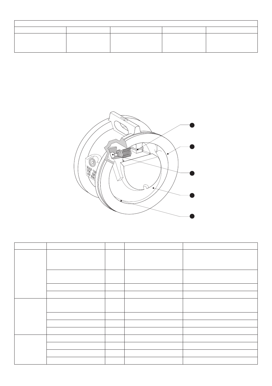
Installation
The flow direction is indicated by an arrow on the lifting lug. Installation in horizontal
lines (lifting lug on top) or vertical lines with upward flow.
Materials
5
) cast steel
4
1
3
2
0