4 installation, 1 quick-check, Mark 100 – Flowserve Valtek Mark 100 Control Valve User Manual
Page 4
Flow Control Division
Mark 100
4
Mark 100 Installation, Operation and Maintenance Instructions
FCD FCAIM0100-02
4 Installation
1. Before installing the valve, clean the line of dirt, welding chips,
scale or other foreign material.
2. Whenever possible, the valve should be installed in an upright
position. Vertical installation permits easier valve maintenance.
a
CAUTION: Do not insulate extension bonnets that are
provided for hot or cold services.
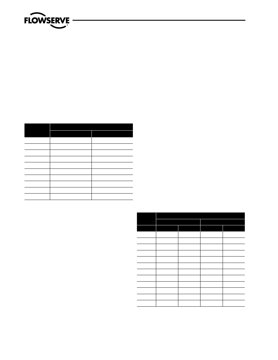
3. Be sure to provide proper overhead clearance for the actuator to
allow for disassembly of the plug from the valve body. Refer to
Table 1 for the necessary clearance needed for valve disassembly.
Table 1: Valve Disassembly Clearance
Valve Size
(inches)
Clearance
inches
mm
6
10
254
8
13
330
10
14
356
12
16
406
14
18
457
16
20
508
18
23
584
20
25
635
24
31
787
30
37
940
4. Double-check flow direction to be sure the valve is installed
correctly. Flow direction is indicated by the arrow attached to the
body.
5. If welding the valve into the line, use extreme care to avoid
excess heat buildup in the valve.
6. Connect the air supply and instrument signal lines. Throttling
control valves are equipped with a valve positioner. Refer to the
appropriate positioner bulletin for connections, maximum air
supplies, and maintenance instructions.
a
CAUTION: On valves equipped with air filters, the air
filter must point down to perform properly.
NOTE: In some rare cases, the air supply must be limited to
less than 150 psi (10.3 bar). This is indicated on a sticker found
near the upper air port on the actuator cylinder. An air regula-
tor should be installed to ensure the supply pressure does not
exceed the line pressure indicated on the sticker.
4.1 Quick-check
Prior to start-up, check the control valve by following these steps:
1. Stroke the valve and observe the plug position indicator on the
stem clamp compared to the stroke indicator plate. The plug
should change position in a smooth, linear fashion.
NOTE: Due to excessive friction, graphite packing can cause the
plug stem to move in a jerky fashion.
2. Check for full stroke by making appropriate instrument signal
change.
3. Check all air connections for leaks.
4. Check packing box bolting for the correct adjustment. Refer to
the packing installation manual for specific details on maintain-
ing the style of packing supplied.
a
CAUTION: Do not overtighten packing. This can cause
excessive packing wear and high stem friction that may
impede plug movement.
5. Make sure the valve fails in the correct direction in case of air
failure. This is done by turning off the air supply and observing
the failure direction.
6. After a temperature excursion has occurred, bonnet flange bolt-
ing should be retorqued to ensure bonnet gaskets do not leak.
See Table 2.
Table 2: Recommended Body Bolt Torque Values
Bolt Size
Bolt/Stud Material
Carbon Steel
Stainless Steel
(inches)
ft-lb
N m
ft-lb
N m
7
⁄
8
230
312
150
203
1
350
474
220
298
1
1
⁄
8
510
691
330
447
11/4
730
990
460
624
1
3
⁄
8
1000
1356
630
854
11/2
1320
1790
840
1139
1
5
⁄
8
1710
2318
1080
1464
1
3
⁄
4
2170
2942
1400
1898
1
7
⁄
8
2700
3660
1700
2305
2
3350
4542
2100
2847
2
1
⁄
4
4050
5491
2530
3430
2
1
⁄
2
4850
6575
3010
4081