Commissioning, Wiring – Flowserve NRG 111-11 User Manual
Page 17
17
Apply mains voltage to level switch NRS 1-7.
Commissioning
Make sure that the electrode NRG 111-11 is connected to the level switch NRS 1-7 according to the
wiring diagram. Fig. 12
Check wiring
Apply mains voltage
Wiring
– continued –
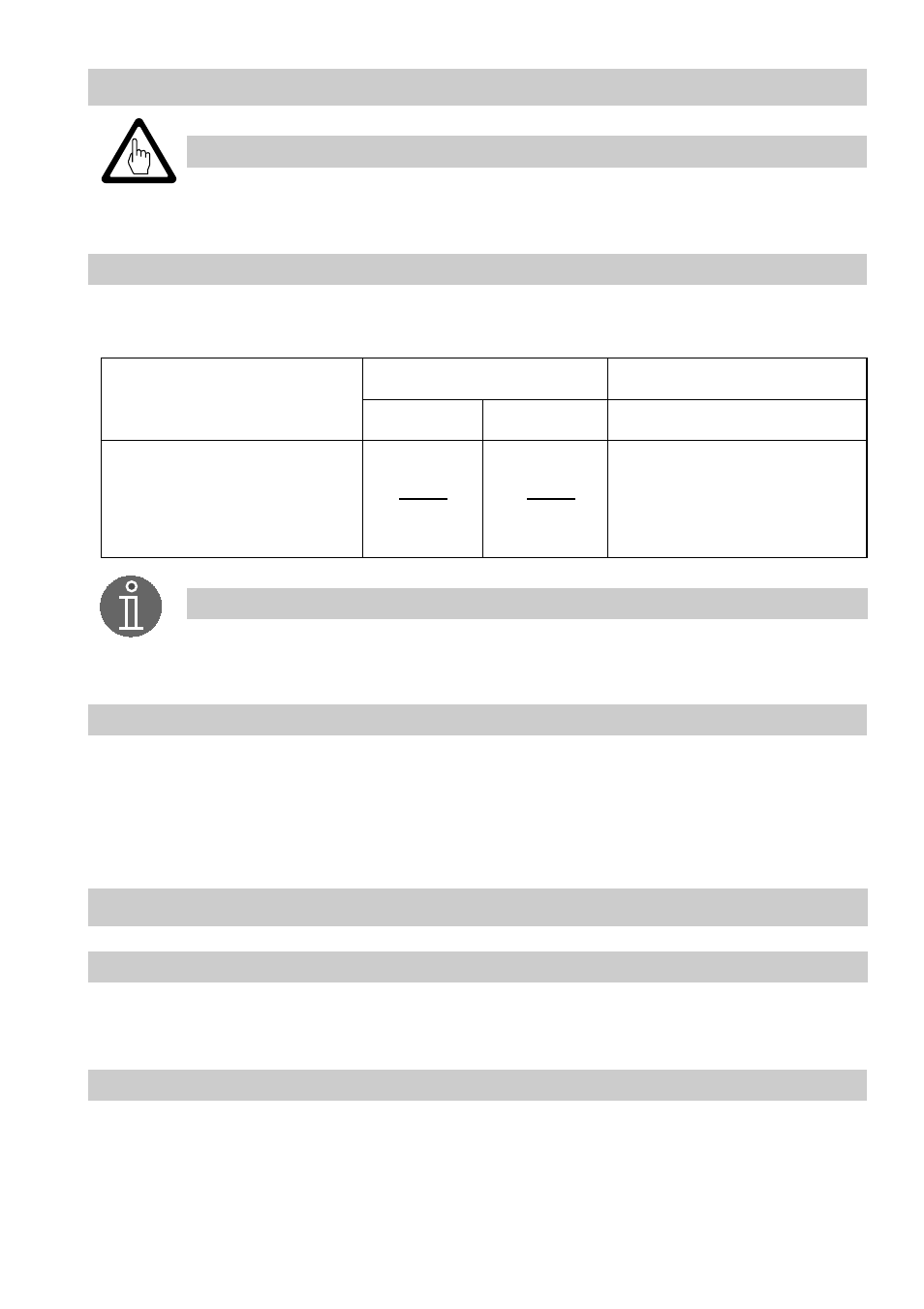
Voltage table
Use this voltage table to check whether the level electrode is submerged or if there is a malfunction.
Observe the wiring diagram of the NRS 1-7, fig. 12
Note
■
The self-checking routine of the amplifier NRS 1-7 reduces U
1-2
every 40 sec.
to 0 volt!
■
Use sealing plug for cable entry L if only one cable runs to the terminal box.
Insert sealing plug supplied with the electrode (IP 65)!
Tools
Attention
■
Screwdriver for cross head screws, size 1
■
Screwdriver for slotted screws, size 2.5, completely insulated according to DIN VDE 0680-1
■
Open-end spanner 18 (19) mm A. F.
U
1-2
10 V
eff
0.5 µS/cm,
C = 0.13 cm
-1
U
1-4
U
2-4
submerged
exposed
malfunction (submerged / alarm)
U
1-2
2
<
U
1-2
2
≥
U
1-4
≤
- Tandem Seal (8 pages)
- 978 Chemiepac (12 pages)
- ISC2 Single Pusher Repair (8 pages)
- LS-300 Series Durametallic (4 pages)
- Pac-Seal Type 16 (8 pages)
- U Series BW Seals (4 pages)
- ISC2 Dual Pusher Repair (12 pages)
- ISC2 Single metal bellows seal (8 pages)
- Durametallic Double CRO (8 pages)
- VRA-C Series Durametallic (4 pages)
- ISC2 Dual metal bellows sea (12 pages)
- Single Inside Pusher Type Seal (8 pages)
- Bearing Gard (2 pages)
- X-200 (12 pages)
- GTS Series (12 pages)
- MSS Series (12 pages)
- SLC Series Interseal (12 pages)
- QB Series BW Seals (8 pages)
- SLM-6100 (12 pages)
- SLM-6200 (12 pages)
- High Temperature Metal Bellows Seals (8 pages)
- X Series BW Seals (8 pages)
- ML-200 Series Durametallic (8 pages)
- ML-200 Series Durametallic (8 pages)
- Circulator (12 pages)
- ISC Series (16 pages)
- Gas Barrier Control System (4 pages)
- CPM Series (8 pages)
- CPM Series (12 pages)
- Mechanical Seal and Seal Support System Storage (4 pages)
- RIS Seal (12 pages)
- 682 Seal Cooler (8 pages)
- ISC2 Series (116 pages)
- ISC2 Series (8 pages)
- Pac-Seal Type 52 (8 pages)
- Pac-Seal Type 31 (8 pages)
- ST Series (8 pages)
- Mechanical Seal General (16 pages)
- Dual Pressurized Seals (8 pages)
- Uniseal Series BW Seals (8 pages)
- XLC Series (8 pages)
- PSS II Durametallic (8 pages)
- PSS II (16 pages)
- ISC1SX (8 pages)
- ISC1PX (8 pages)