Flowserve 520MD Digital Positioner User Manual
Page 8
8
®
User Instructions Logix 520MD - LGENIM0520-01 09/09
Ensure proper wiring and shielding techniques of the
control lines, and route control lines away from elec-
tromagnetic sources that may cause unwanted noise.
An electromagnetic line filter can be used to further
eliminate noise (FLOWSERVE Part Number 10156843).
In the event of a severe electrostatic discharge near
the positioner, the device should be inspected to
ensure correct operability. It may be necessary to
recalibrate the Logix 520MD positioner to restore
operation.
9 STARTUP
9.1 Logix 520MD Local interface
The Logix 520MD local user interface allows the user
to configure the basic operation of the positioner, tune
the response, and calibrate the positioner without
additional tools or configurators. The local interface
consists of a Quick-Cal™ button for automatic zero and
span setting, along with two jog buttons for spanning
valve/actuators with no fixed internal stop in the open
position. There is also a switch block containing eight
switches. Six of the switches are for basic configuration
settings, two are for calibration options. There is also
a rotary selector switch for adjusting the positioner
gain settings. For indication of operational status or
alarm conditions there are three LEDs on the local user
interface.
9.2 initial DiP Switch Setting
Before placing the unit in service, set the DIP switches in
the “Configuration” and “Cal” boxes to the desired control
options.
nOTE: The switch settings in the Configuration box are
activated only by pressing the Quick-Cal button or by
utilizing the stroke calibration features provided by a
handheld or by Flowserve PC software.
9.2 Operation of Configuration DiP Switches Setup
The first six DIP switches are for basic configuration
1. Air Action – Must be set to match the configuration of
the valve/actuator mechanical configuration.
ATO (air-to-open) – Select ATO if increasing output pres-
sure from the positioner is tubed so it will cause the valve
to open.
ATC (air-to-close) – Select ATC if increasing output pres-
sure from the positioner is tubed so it will cause the valve
to close.
2. Signal at Closed – Normally this will be set to 4 mA for
an air-to-open actuator, and 20 mA for an air-to-close
actuator configuration.
Selecting 4 mA will make the valve fully closed when the
signal is 4 mA and fully open when the signal is 20 mA.
Selecting 20 mA will make the valve fully closed when the
signal is 20 mA and fully open when the signal is 4 mA.
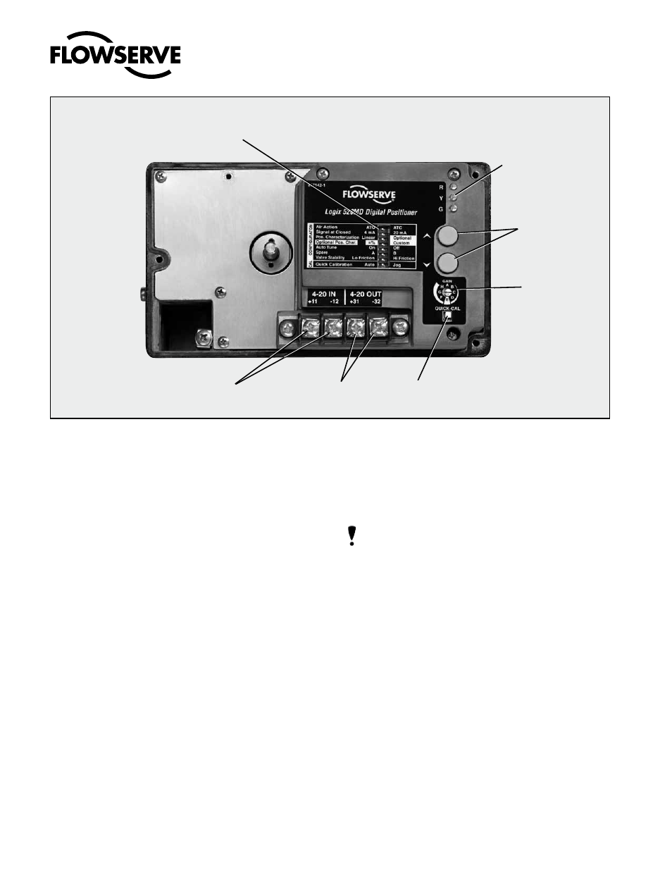
Figure 4: Logix 520MD Local interface
4-20 mA Input
4-20,mA Feedback
(Optional)
Quick-Cal Button
Gain Selector
Jog Calibrate
Buttons
LED Status
Lights
Configuration Switches