Flowserve KV10 Outer Butterfly Valve User Manual
Page 3
Important Safety Note
Danger
Do not carry out any installation or
maintenance work unless the tank container
is completely empty and degassed.
Escaping vapours and gas can endanger life
and health of the person responsible for
installation and maintenance and cause
material damage.
Do not hold the device by means of the
operating lever.
Butterfly valves for tank containers must only
be installed by qualified staff.
Carefully read through installation instructions
before mounting the valve.
Use GESTRA genuine spare parts only.
3
Function
Butterfly valve (outer valve) with operating
lever for loading and unloading systems for
hazardous tank containers of IMO classes 1
and 2.
Opening:
Turn operating lever
A
anticlockwise through
90° and snap into position.
Closing:
Turn operating lever
A
clockwise through 90°
and snap into position.
Design
■
Main components:
Body for installation between flanges
Stem
Disc
Operating lever
Seat ring and gasket
■
Ancillary components:
Heating jacket
Hemisphere (as closure device)
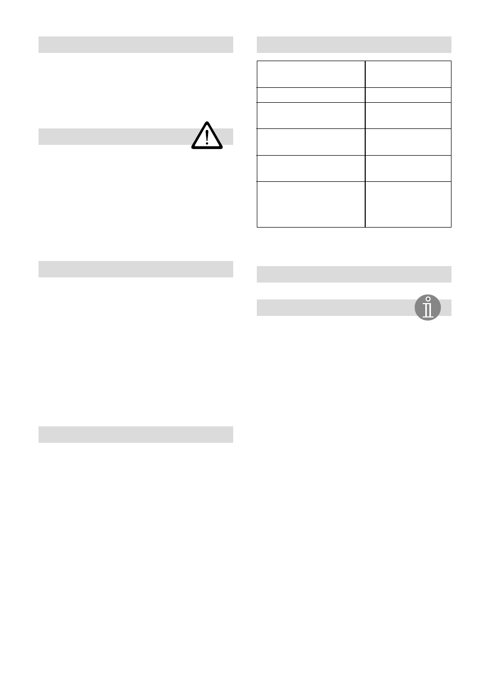
Technical Data
Pressure/Temperature
Ratings
DN/NPS
80/3"
Service pressure
[bar]
6
[psig]
87
Min. service temp. [°C]
–10
Max. service temp. [°C]
190
Test pressure
[bar]
10
[psig]
145
Connection
For dimensions and further specifications
see data sheet.
Installation
The disc must be in the closed position when
installing the valve.
Fitting (Fig. 1)
1. Introduce two hexagon-head bolts
T
through bottom holes of the square flange
and place guide sleeves
V
onto bolts.
2. Introduce now the bolts with sleeves
T
and
V
through bottom holes of the CV 10
flange and secure with two nuts
U
.
3. Place the closed butterfly valve type KV 10
onto the two guide sleeves.
4. Put gaskets
W
and
X
between the KV 10
guide sleeves
V
and flanges. The gaskets
must be flush with the valve.
5. Introduce hexagon-head bolt
T
through top
left hole of the square flange.
6. Introduce this bolt
T
through the
corresponding hole of the CV 10 flange and
secure with nut
U
.
7. Proceed in the same way with top right
hexagon-head bolt.
8. Align the valve KV 10 and tighten nuts
manually. Take care that the gaskets are
flush with the valve.
9. Tighten the hexagon-head bolts
T
and nuts
U
gradually and in diagonally opposite
pairs with a torque of 80 ± 5 Nm.
Wafer design for
installation between
flanges with
centering sleeve
Important Note