Flowserve 505si Series Digital Positioner User Manual
Page 7
7
®
User Instructions Logix 505si - LGENIM0505-00 03/09
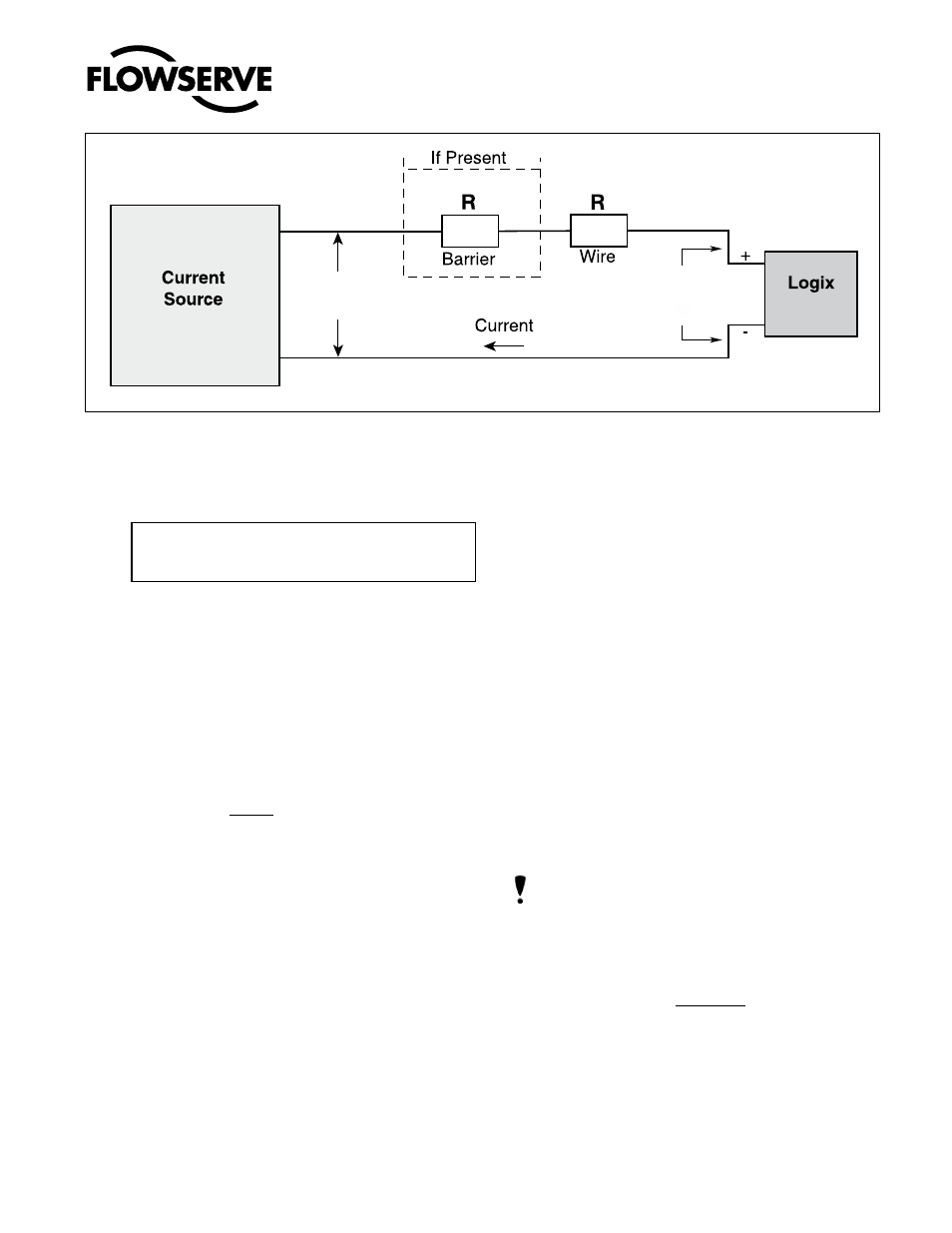
In order to determine if the loop will support the Logix
505si, perform the following calculation:
Available Voltage = Controller Voltage (@Current
MAX
)
- Current
MAX
*(R
barrier
+ R
wire
)
The calculated available voltage must be greater than
6.0 VDC in order to support the Logix 505si.
Example: DCS Controller Voltage = 19 V
R
barrier
= 300
Ω
R
wire
= 25
Ω
CURRENT
MAX
= 20 mA
Voltage = 19 V - 0,020 A*(300
Ω + 25 Ω)
= 12,5 V
The available voltage 12,5 V is greater than the required
6.0 V; therefore, this system will support the Logix
505si. The Logix 505si has an input resistance equivalent
to 300
Ω at a 20 mA input current.
The Logix 505si digital positioner has been designed to
operate correctly in electromagnetic (EM) fields found
in typical industrial environments. Care should be taken
to prevent the positioner from being used in environ-
ments with excessively high EM field strengths (greater
than 10 V/m). Portable EM devices such as hand-held
two-way radios should not be used within 30 cm of the
device.
Ensure proper wiring and shielding techniques of the
control lines, and route control lines away from elec-
tromagnetic sources that may cause unwanted noise.
An electromagnetic line filter can be used to further
eliminate noise (FLOWSERVE Part Number 10156843).
In the event of a severe electrostatic discharge near the
positioner, the device should be inspected to ensure
correct operability. It may be necessary to recalibrate
the Logix 505si positioner to restore operation.
8
STARTUP
8.1
Logix 505si Local interface Operation
The Logix 505si local user interface allows the user to
configure the operation of the positioner, tune the re-
sponse, and calibrate the positioner. The Local interface
consists of a quick calibration button for automatic zero
and span setting. There is also a switch block contain-
ing 4 switches. For indication of the operational status
or alarm conditions there are 3 LEDs on the local user
interface. This document describes the setting and use
of the Logix 505si user interface.
8.2
initial DiP Switch Setting
Before placing the unit in service, set the DIP switches
to the desired control options. For a detailed description
of each DIP switch setting, see sections below.
nOTE: The switch settings except the gain modifier
are activated only by pressing the Quick-Cal button.
The gain modifier switch is active at all times.
Operation of COnFigURATiOn DiP switch Setup
a.
Air Action - This must be set to match the configuration
of the valve/actuator mechanical tubing connection and
spring location since these determine the air action of
the system.
• ATO (air-to-open)- Selecting ATO if increasing
output pressure from the positioner is tubed so
it will cause the valve to open.
• ATC (air-to-close)- Selecting ATC if increasing
output pressure from the positioner is tubed so
it will cause the valve to close.
Figure 3: Compliance Voltage
510
Controller
Voltage
Compliance
Voltage
12V
505si
6V