Flowserve Valtek Torex TX IOM User Manual
Page 7
Torex TX VLEEIM4143-02 09.10
7
9. Close the disc for centering the seatring, screw down
the retainer ring to keep the seatring in place.
10. Check that the seatring is centered. The play
shall be evenly applied between the disc and the
body.
Start to fasten the retainer ring by crosswisely
changing screws with evenly applied force.
11. The retainer ring shall more or less flush with the
valve body. If not, gently hammer with a plastic
hammer at the same time as the screws are
tightened.
12. Now you can mount the actuator and adjust the
end positions of the actuator until you get the
correct A-measure. This is described separately
below.
The valves seat ring should now be correctly prepared and
should not leak. Please note that PTFE can leak before it
becomes warm and adjusts to the disc. This is however a
small leakage and should not be considered. The valve
will be tight shortly.
9.4 To adjust a new seat ring in a valve with
manual operating lever or worm gear unit
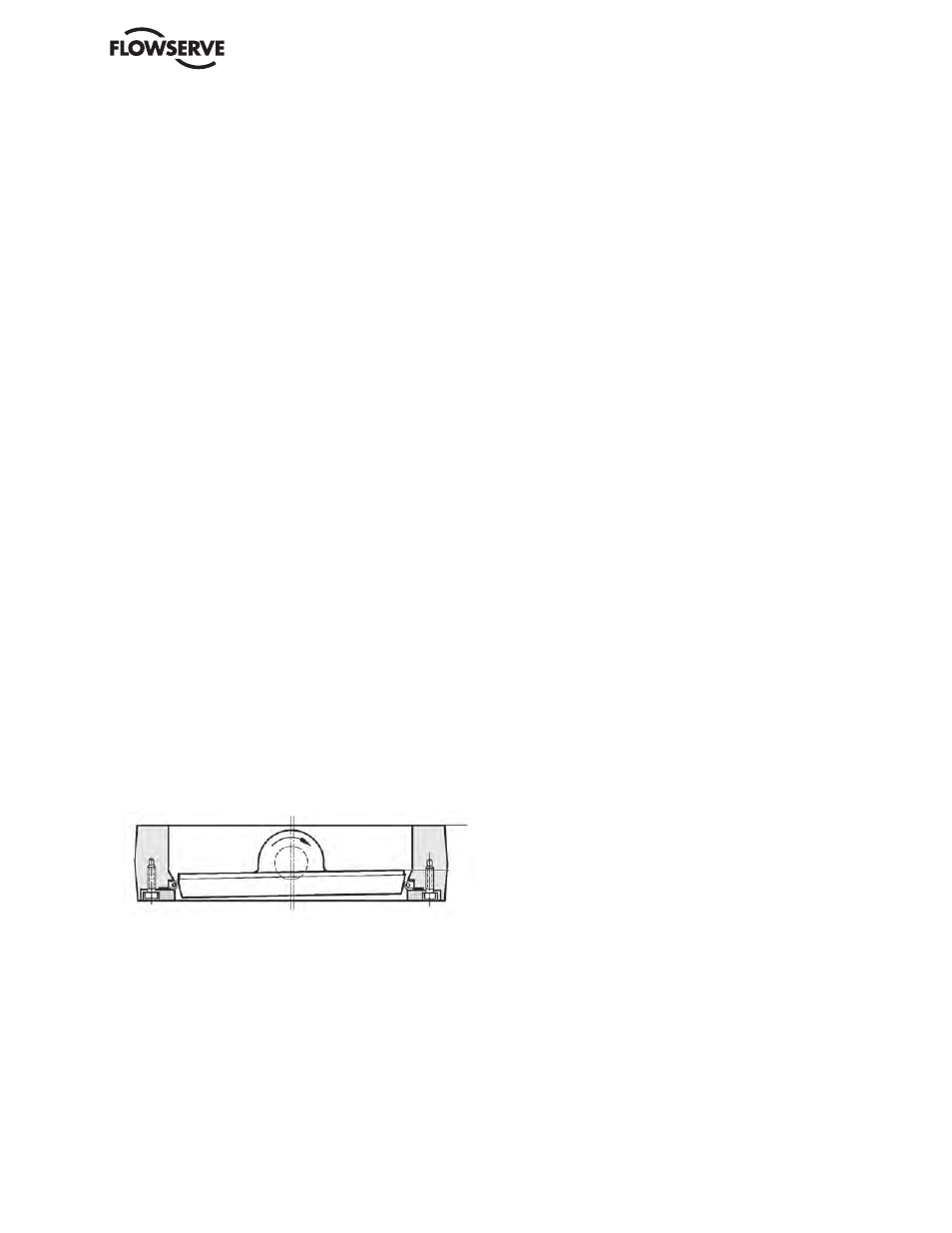
1. Close the valve to the sealing position corresponding to
the value of dimension ”A” shown in Fig. 4.
2. Adjust the end stop of the operating lever or the worm
gear unit so that the sealing position will not be exceeded.
3. Tighten the retainer ring bolts in diagonally opposite pairs.
9.5
To adjust the seat ring in a valve with
pneumatic actuator
1. Turn the valve to closed position, although without
applying a sealing torque. The valve disc should then
only just be in contact with the seat ring in the valve
body.
2. Adjust the end position stop to the position in which the
valve is almost closed.
3. Connect the compressed air supply to the actuator. If
the end position stop is correctly set, the valve disc will
not move.
4. Adjust the end position stop until the actuator has
turned the valve disc to the sealing position, i.e.
dimension ”A” shown on the valve in accordance with
section 9.4 and Fig. 4.
5. Lock the end position stop so that the sealing position
will not be exceeded.
6. Tighten the retainer ring bolts.
9.6
To inspect and replace the upper stem seal:
9.6.1 Boxpacking of graphite type
The boxpacking usually requires inspection and adjustment
after the valve has been taken into service.
Ensure that the valve is not under pressure.
1.
Remove the actuator.
2.
Remove the nuts (29) and remove the gland
cover (23) and the boxpacking set (21).
3.
Clean the surfaces of the stem, gland cover (23)
and recess in the valve body.
4.
Carefully examine the stem surface which
must be completely free from marks and
scratches.
5.
Fit new boxpacking set (21). Then fit the gland
cover (23) and the nuts (29).
6.
Tighten the nuts (29) sufficiently to ensure that
the boxpacking is correctly seated and that it is
in contact with both the stem and the valve body.
Note: Check the condition of the boxpacking and, after the
valve has been taken into service, retighten the nuts (29), if
necessary.
Fig. 4. Adjusting a new seat ring.