Flowserve Valtek Beta Positioners for Control Valves User Manual
Page 5
24-5
Flowserve Corporation, Valtek Control Products, Tel. USA 801 489 8611
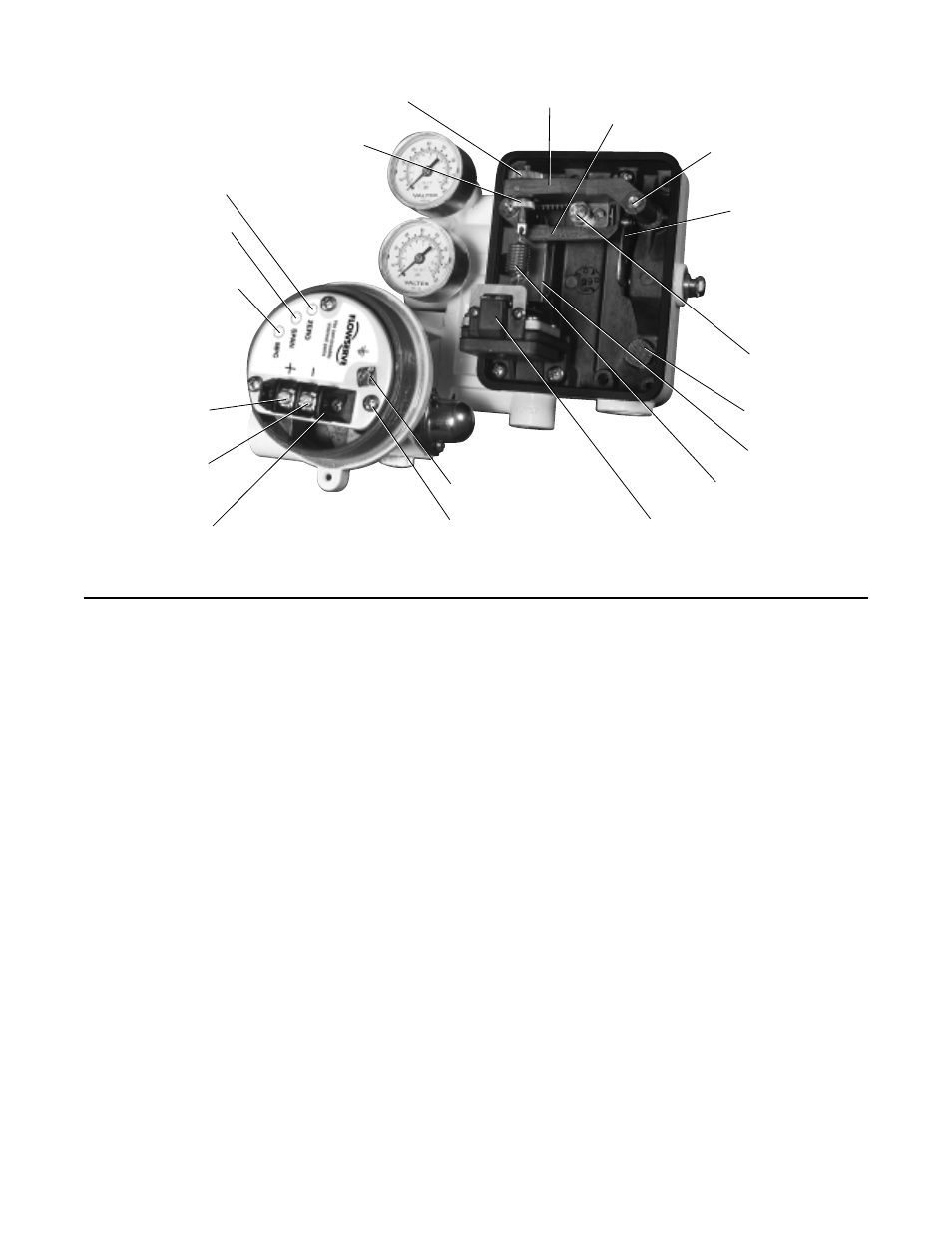
Figure 7: Beta Positioner with NT 3000 Transducer
3. If not welded to the stem clamp, bolt the take-off arm
to the stem clamp so that the arm curves upward
(toward the cylinder). The holes in the follower arm
(31) should line up with the slots in the take-off arm
(again refer to Figure 3).
4. Referring to Figure 6, install the cam (27), cam shaft
(29) and follower arm (31) for the proper air action.
For air-to-open action, the cam should be installed
with the letters L-R facing toward the cam shaft and
the return spring should be fed into hole “A.” For air-
to-close action, the L-D side of the cam should face
toward the cam shaft and the return spring should
be fed into hole “B.”
5. Feed the appropriate stroke follower arm (31) onto
the cam shaft boss (29) with the hole markings
facing outward. Fasten securely with the lock
washer (32) and nut (33).
6. Mount positioner on the bracket. Connect the
follower arm (31) and take-off arm together with
follower pin (62). Connection must allow free
movement of follower arm.
CAUTION: Be certain to lubricate the follower
pin and take-off arm where contact is made to
prevent premature wear. A light industrial
grease is recommended. Failure to do so can
cause premature wear, resulting in equipment
failure and possible personal injury.
7. For air-to-open (air-to-retract) air action, tube “out-
put 1” to the bottom and “output 2” to the top of the
cylinder. For air-to-close (air-to-extend) action, tube
“output 2” to the bottom and “output 1” to the top of
the cylinder.
8. Attach air supply and instrument tubing, using
1
/
4
-
inch NPT tubing connections.
CAUTION: A 3-15 psi instrument signal is rec-
ommended on the pneumatic module. High air
pressure may damage the module; the module
is limited to 30 psi.
Reversing Air Action on Linear Actuators
Reversing the air-action of the positioner is simple. No
additional parts are required, although the tubing will
need to be rerouted on the linear actuator.
To reverse the air-action on all sizes of Valtek linear
actuators:
1. Using Installation, Operation, Maintenance Instruc-
tions 2, reverse the air-action of the actuator.
2. Disengage the return spring from the cam and
remove the cam from the cam shaft.
3. Reverse the cam, return spring, and tubing for the
desired air-action by referring to steps 4-8 in the
“Installing Positioner on Linear Actuators” section of
this bulletin.
Zero Adjustment
Span Adjustment
Minimum Pressure
Cutoff Adjustment
Current Loop
Termination (+)
Current Loop
Termination (-)
Terminal Block
Range
Adjustment
Gear
Vent Screen
Spool Valve
Grounding Screw
Zero Adjustment Knob
Range Arm
Cam
Zero Adjustment Locking
Zero Arm
Range Adjustment
Locking Screw
Feedback Spring
Instrument Signal
Capsule
Mounting Screws