Figure 2: positioner mounting bracket, Figure 3: return spring / cam mounting, Figure 1: xl positioner schematic for air-to-open – Flowserve XL Series High-Performance Positioner User Manual
Page 2
45-2
Flowserve Corporation, Valtek Control Products, Tel. USA 801 489 8611
Size 25, 100, 200 Size 50
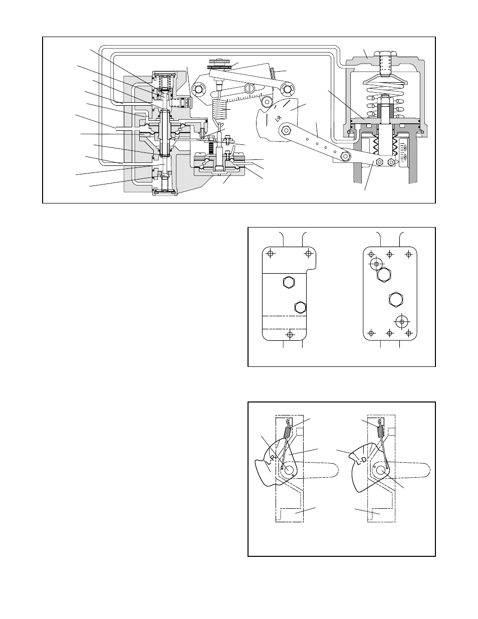
Figure 2: Positioner Mounting Bracket
Air-to-Open
Air-to-Close
(Air-to-Retract)
(Air-to-Extend)
Figure 3: Return Spring / Cam Mounting
(viewed from positioner’s right side)
Positioner
Base
Return Spring
Hole B
Cam
Hole
A
change the output pressures, moving the stem until the
tension on the feedback spring opposes exactly the
instrument signal pressure.
The sequence of operation is as follows: An increase in
instrument signal pressure forces the input capsule
downward. Displacement of the capsule in turn moves
the flapper away from the detecting nozzle. This allows
a larger flow rate through the nozzle, decreasing the
pressure exerted on the top of the pilot valve capsule.
Supply air biases the pilot-valve in an upward direction.
As the capsule moves up, it will close the exhaust seat
of the upper pilot poppet and open the supply seat,
which applies increased air pressure to the bottom
cylinder port. At the same time, the pilot-valve capsule
will open the exhaust seat for the lower pilot poppet;
thus, decreasing pressure to the top cylinder port.
This difference in pressure will drive the piston upward,
which stretches the feedback spring until the spring
tension exactly opposes the force resulting from the
instrument signal pressure. At this point, the flapper will
be moved toward the detecting nozzle to restore the
pressure above the pilot-valve capsule to its equilibrium
value. As a force-balanced condition is approached, the
pilot-valve capsule will be forced back to a neutral
position where the pilots are neither supplying air to, nor
exhausting air from, their respective sides of the piston.
A decrease in instrument signal pressure reverses the
described actions and causes a proportional downward
movement of actuator piston and stem.
Installation of XL Series Positioner on
Double-Acting, Linear-Cylinder Actuators
When installing or retrofitting the XL Series positioner
on all sizes of linear actuators, proceed as follows:
NOTE: For retrofitting to an actuator equipped with
a Beta or 80R positioner, the same bracket, follower
arm and take-off arm can be used (begin with step 4).
Figure 1: XL Positioner Schematic for Air-to-Open
O
S
Supply Seat
Upper Pilot
Poppet
Exhaust Seat
Port No. 1
Restriction
Supply
Pilot Valve
Capsule
Exhaust Seat
Port No. 2
Lower Pilot
Poppet
Supply Seat
Input Capsule
Upper Diaphragm
Instrument Signal
Lower Diaphragm
Take-off Arm
Balance Adjustment
Zero Adjustment
Range
Adjust Screw
Cam
Feedback
Spring
Follower
Arm
Flapper
Detecting
Nozzle
Piston
Cylinder