Flowserve Limitorque QXM Linear Base User Manual
Page 4
MXa/QXM Linear Base FCD LMENIM2315-00 – 6/14
4
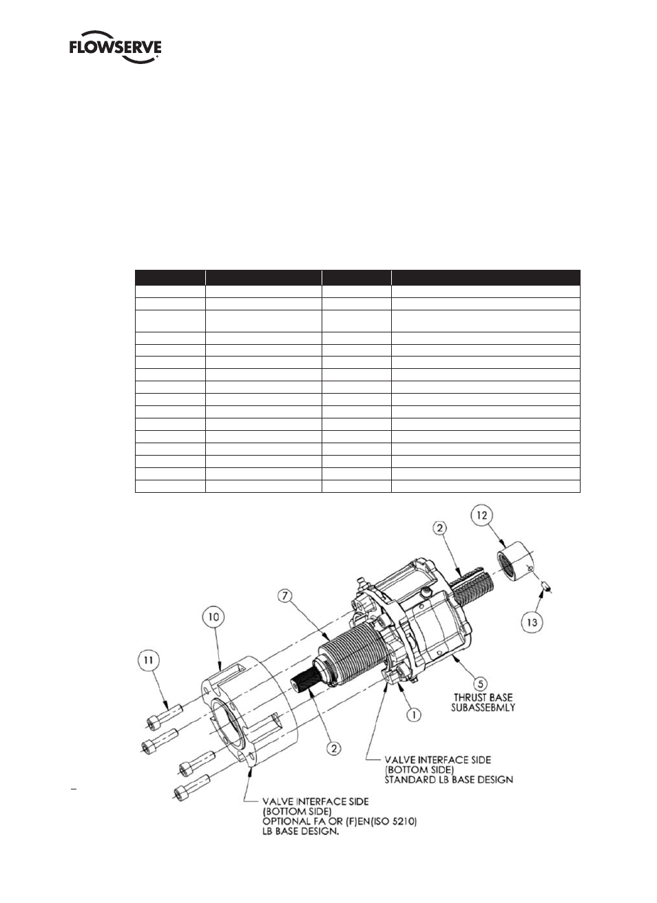
1.1.2 Optional LB FA or EN (F) Base and Stop Nut Subassembly
NOTE: The EN (F) base meets standard DS/EN 15714-2 but has the same mounting as an ‘F’ ISO style base.
Step 1
(Optional Stop Nut if supplied) Remove set screw (#13) and spin nut (#12) off shaft.
NOTE: Optional nut may only be used when LB is mounted to a QXM, MX-10 or MX-40 actuator.
Step 2
(Optional FA/EN (F) base) Remove the four bolts (#11) that secure the optional base to the anti-rotation base (#1) and
slide the base off over shaft (#2) and bellows (#7).
Figure 1.2 – Optional LB FA/EN (F) Base and Stop Nut Subassembly
LB1 assembly shown in this figure.
Table 1.1 – Optional LB1 and LB2 Subassembly
ITEM NUMBER
DESCRIPTION
QTY.
NOTES
1
ANTI-ROTATION BASE
1
2
SHAFT
1
3
THRUST NUT
1
PART OF THRUST BASE ASSEMBLY, BUT MACHINED
TO MATE WITH LB ASSEMBLY
4
SOCKET HEAD CAP SCREWS
4
5
THRUST BASE ASSEMBLY
1
6
GASKET
1
7
BELLOWS AND TWO CLAMPS
1
8
GREASE FITTING
1
9
PIPE PLUG
1
10
OPTIONAL FA OR EN (F) BASE
1
11
SOCKET HEAD CAP SCREWS
4
12
OPTIONAL STOP, HW CLOSED
1
QXM, MX-10 AND MX-40 ONLY
13
SET SCREW, OPTIONAL STOP
1
QXM, MX-10 AND MX-40 ONLY
14
ANTI-ROTATION NUT
1
LB2 ONLY
15
O-RING
1
LB2 ONLY
16-16
SPACER, PILOT
1
SEE NOTES FOR USAGE