Flowserve McCANNA CryoSeal Ball Valves User Manual
Page 12
McCANNA CryoSeal
®
Ball Valves FCD MMENIM2007-01-AQ – 04/15
12
5.5 Install O-rings and back-up rings into metal cartridge. Back up rings have a flat side and concave
side. Concave side is to be facing the o-ring. Ensure that back-up rings do not become twisted
during assembly. There will be 4 O-rings in a cartridge (2 on the OD and 2 on the ID). Install the
smaller O-rings and back-up rings on the inner diameter of the cartridge, and the larger O-rings
and back-up rings on the outer diameter of the cartridge.
5. 6 Insert o-ring cartridge into packing bore. O-rings are to be at the bottom of each groove, with a
back-up ring on top of each o-ring. See Figure 4 for correct orientation.
5. 7 Install the gland follower into the packing bore. This follower has a step with a smaller inner
diameter on one side. The step should be placed at the top.
5. 8 Place adjuster onto top adjuster studs. The rounded rocker portion of the adjuster will be in
contact with the gland follower.
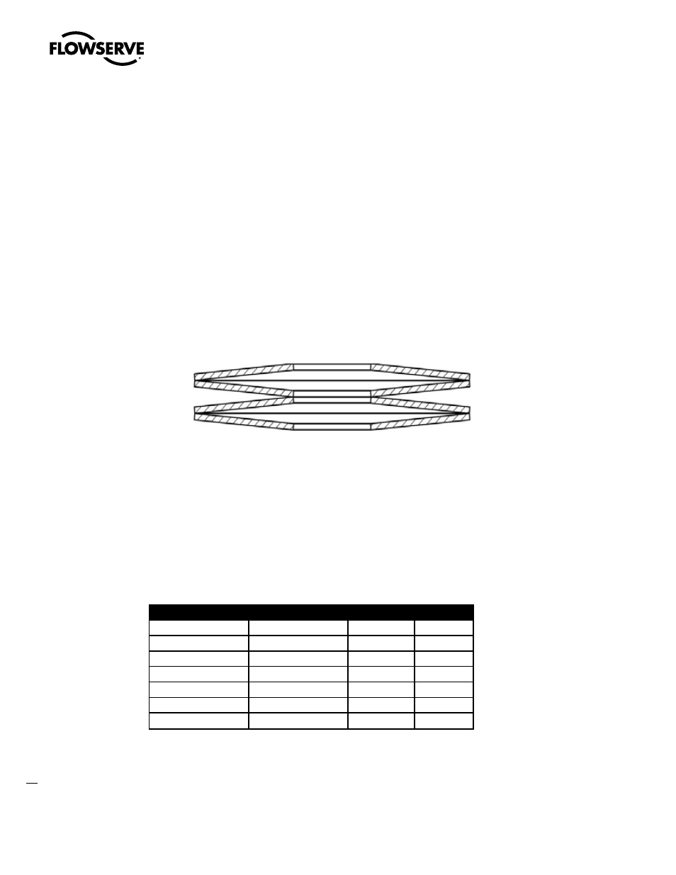
5. 9 Install Belleville washers on adjuster studs. An equal number of washers will be on each adjuster
stud. Pairs of Belleville washers are to be installed cup-to-cup. See Figure 5 for correct orientation
Figure 5. Belleville Washer
5. 10 Tighten nuts onto adjuster bolts finger tight. This is not to compress the packing, but only to hold
it in place during stem insertion.
5. 11 Slide the lower thrust bearing washer onto the stem. This will be above the blowout proof step on
the stem.
5. 12 Insert stem into bonnet, taking care not to scratch the stem or damage the packing. Ensure that
when the bonnet is placed on the body, the stem will be in the open position.
5. 13 Torque adjuster nuts to proper torque value specified in Table 2.
Table 2 - Minimum Torque Requirements for Adjuster Bolts
Recommended Torque (ft-lbs)
Regular Port Valve Size
Full Port Valve Size
Class 150/300
Class 600
1.5
0.5, 0.75, 1
15
15
2
1.5
15
15
3
2
15
15
4
3
40
40
6
4
40
40
8
6
40
40