Flowserve Valtek Valdisk Control Valves User Manual
Page 3
10-3
PREVENTIVE MAINTENANCE
At least once every six months, check for proper operation by
following the preventive maintenance steps outlined below.
These steps can be performed while the valve is in line and,
in some cases, without interrupting service. If an internal
problem is suspected, refer to the ìDisassembly and Reas-
semblyî section.
1. Look for signs of gasket leakage through body and line
flanges. Tighten flange bolting if necessary.
2. Note if any corrosive fumes or process drippings are
damaging the valve.
3. Clean valve and paint any areas of severe oxidation.
4. Check packing box bolting for proper tightness. Packing
nuts should be slightly over finger-tight; however, tighten
as necessary to prevent stem leakage.
CAUTION: Do not overtighten packing.
5. If valve is supplied with a lubricator, check lubricant supply
and add lubricant if necessary.
6. If possible, stroke valve and check for smooth, full-stroke
operation by observing the disc position indicator plate
mounted on the transfer case. Unsteady movement of
the disc could indicate an internal valve problem (jerky
motion is normal whenever Grafoil packing is used).
7. Check positioner calibration by observing the gauges and
the disc position indicator plate. Make sure the positioner
is calibrated to the correct range. Push the positioner
cleanout plunger (Model 80R positioner only) several
times to clear any possible restrictions.
8. Remove transfer case cover plate and make sure the
positioner linkage and internal actuator parts are securely
fastened. Also, check for air leaks through actuator stem
seal, using a soap solution.
CAUTION: Never apply air to the actuator without the
cover plate installed; otherwise, the unsupported shaft
may sustain damage.
9. Be sure that all accessories, brackets and bolting are securely
fastened.
10. If possible, remove air supply and observe stroke plate
for correct fail-safe action.
11. Spray soap solution around the cylinder retaining ring
and the adjusting screw to check for air leaks through
the O-rings.
12. Clean any dirt or other foreign material from the exposed
portion of the shaft.
13. If an air filter is supplied, check and replace cartridge if
necessary.
DISASSEMBLY AND REASSEMBLY
Removing Valve From Line
If an internal problem is suspected with the valve and disas-
sembly is required, remove the valve from the line by proceed-
ing as follows:
WARNING: Depressurize line to atmospheric pressure, drain
all process fluids and decon-taminate the valve (if caustic
or hazardous materials are present). Failure to do so can
cause serious injury.
1. Make sure valve is fully closed.
Note: On valves with fail-open action, air pressure must
be supplied under the actuator piston to close the valve.
If the valve is supplied with a handwheel, it can be used
to close the valve.
2. Attach a hoist or some means to support the valve.
3. Remove the line bolting. Do not attempt to pry line flanges
apart by pushing or pulling on valve actuator.
4. Slide the valve carefully from the line. To avoid damage
to gasket surfaces, do not twist the valve.
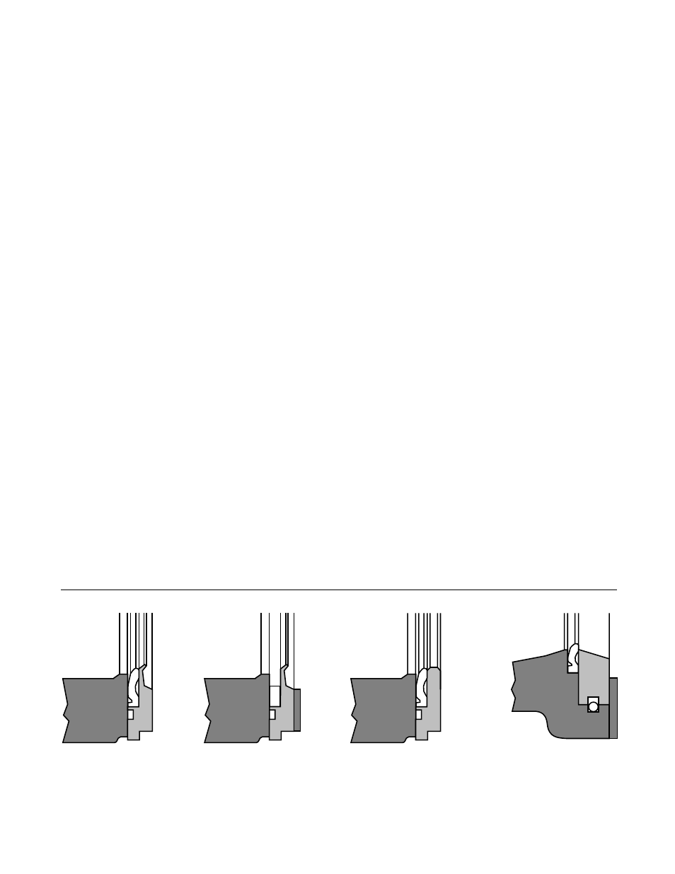
Figure 1: Seat Retainer Configurations
NOTE: Item numbers correspond directly to the bill of material. Refer to the bill of material for specific part numbers.
A ñ Dual Seat
B ñ Metal Seat
C ñ Soft Seat
D ñ Seat Insert /
Snap-ring