0 valve description, 1 recommended uses, 2 principles of operation – Flowserve Double-Disc Gate Valve Sizes 2.5 User Manual
Page 4: 3 design features
Anchor/Darling Double Disc Type Gate Valves FCD ADENIM0003-01 - 07/14
4
1.0 Valve Description
1.1 Recommended uses
Anchor/Darling Double Disc gate valves are designed to provide
isolation of a piping system or a component when closed. They are not
suitable for modulation of flow; i.e., throttling, and should not be used
for that purpose.
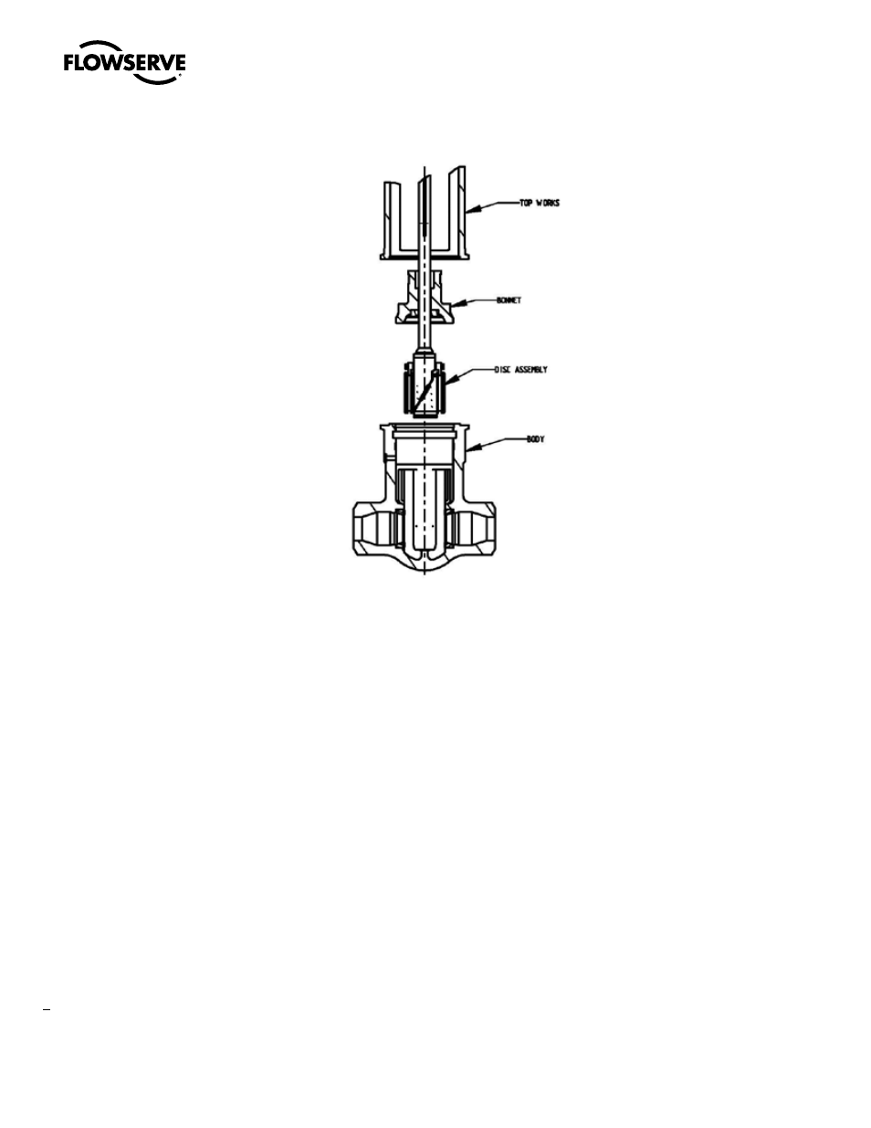
1.2 Principles of operation
The principle parts of a double disc valve are the body, bonnet, disc
assembly, stem and top works (Fig. 1). The body and bonnet contain
the fluid within the system. The disc assembly is positioned by the
stem to either block flow through the body or is raised to leave an
unobstructed flow passage.
The disc to seat seal in the double disc gate valve is created by a
combination of internal pressure and mechanical wedging force. When
the line pressure is high, the differential between the upstream and
downstream ports forces the downstream disc against the downstream
seat and creates a seal. At lower line pressures (under approximately
100 psi), the pressure force alone may not be sufficient to create a seal.
A mechanical force resulting from the discs being expanded against
the seat rings by wedging mechanism between them provides the
additional force necessary to seal.
1.3 Design features
1.3.1 Bonnet Seals: Anchor/Darling Double Disc Gate valves are
supplied with two basic types of body-bonnet closures; bolted
bonnet or pressure seal.
The bolted bonnet closure (Fig. 2) is a bolted flange tongue
and groove joint with spiral-wound stainless steel gasket with
graphite filler. The seal depends on the bolt preload to maintain
sufficient compressive force on the gasket.
Pressure seal type closures (Figs. 3 & 4) utilize a tapered soft
metal or graphite gasket for sealing. The gasket is contained
within the body neck bore by a retaining ring. The tapered inner
surface of the gasket bears against a mating annular surface on
the valve bonnet. Under internal pressure, the bonnet is forced
against the pressure seal gasket, wedging it against the body
neck wall. A slight interference angle produces a line contact
Figure 1