Reversing position transmitter signal, Table iv: specifications – Flowserve Valtek Position Pac User Manual
Page 6
29-6
Flowserve Corporation, Valtek Control Products, Tel. USA 801 489 8611
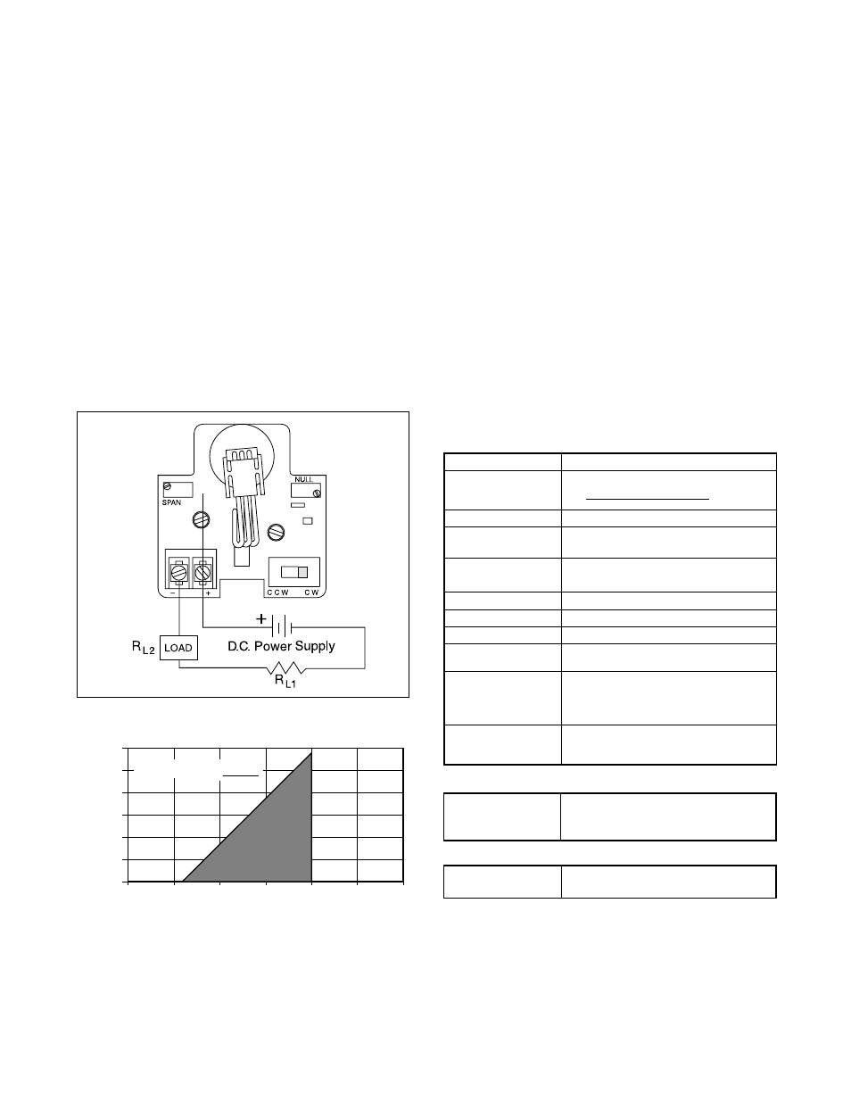
Figure 6: Wiring Diagram
Figure 7: Power Supply Requirements
9b. Set the ZERO and SPAN potentiometers to their
approximate middle position. This is accomplished
by first turning each potentiometer clockwise 25
turns or until a ‘click’ is either felt or heard. Then turn
each potentiometer counterclockwise approxi-
mately 12 complete turns. Repeat steps 2 through 8
to complete calibration.
10. Replace the housing cover.
REVERSING POSITION TRANSMITTER
SIGNAL
The following instructions should be used when the sig-
nal being transmitted from the position transmitter is
either incorrect or needs to be reversed. Refer to
Figure 5.
1500
1250
1000
750
500
250
0
0 10 20 30 40 50 60
Max. Load Resistance, R (
Ω
)
L
Power Supply Voltage, V (volts)
PS
Operating
Region
R = V - 12.5V
20 mA
L max PS
Table IV: Specifications
Analog Output
Power Supply Range
12.5 to 40 VDC (24V DC typical)
Maximum Load
Maximum Resistance (ohms) =
Resistance
Supply Voltage - 12.5
(see Figure 3)
0.02
Current Signal Output 4-20 mA
Span
Adjustable from 5
°
to 100
°
of angular
rotation
Null
4 mA position may be set at any angular
position
Linearity
±
1.0% full-scale*
Repeatability
±
0.25% full-scale
Hysteresis
±
1.0% full-scale
Operating
-40
O
to 185
O
F (-40
O
to 85
O
C)
Temperature Range
Ambient Temperature For a 100
O
F (38
O
C) change in ambient
Range
temperature, maximum zero shift is
±
0.4% full scale, maximum span
shift is
±
0.7% full scale
Power Supply
Output signal changes less than
0.05% when supply voltage is varied
between 12.5 and 40 volts dc
Limit Switches
(SPDT)
20 amps, 125, 250, 480 VAC, ind. and
UL/CSA Rating (L23)
res. 1 Hp. 125 VAC; 2 Hp, 250 VAC, 0.5
amp. 125 VDC; 0.25 amp, 250 VDC res.
Mechanical
Input motion
±
105
O
from the center; spring
loaded to return to the center
* Linearity is
±
1.0% for 90
O
rotary shaft input. When mounted to
linear travel valves, linearity is dependent on linkage design and
stroke length. Typical linearity is
±
1.5% full-scale on Valtek Mark
One control valves.
NOTE: Instructions within parenthesis ( ) refer to older
Position Pac models characterized by a white label.
1. Remove the housing cover.
WARNING: On explosion-proof installations,
disconnect electrical power or be certain the
area is safe from combustible atmospheres be-
fore removing the housing cover.
2. Locate the switch next to the position transmitter’s
wiring terminal. Move switch to the opposite posi-
tion, CCW or CW (DIR or REV). Repeat steps 3-9 in
the
Calibration section for the position transmitter.
NOTE: The SPAN potentiometer will generally not
need readjustment.
3. Replace the housing cover.