3 piping – Flowserve X-100 User Manual
Page 6
6
3 Piping
Consult your Flowserve Sales and Service Representative or Flowserve
Authorized Distributor for assistance in selection of seal environmental
control plans. Usually one of three flush plans is used:
3.1 ASME Flush Plan 7302, dead-ended, may provide adequate
removal of seal generated heat if the pump is equipped with an
enlarged seal chamber or if the shaft speed and chamber pressure
is low. If no flush is used, plug flush port
a
, Figure 7.
To maximize seal life, Flowserve recommends that a product bypass
or clean external flush be used whenever possible with a X-100 seal
installed in a conventional seal chamber such as a converted stuffing
box.
3.2 ASME Flush Plan 7311, product bypass flush, is piped from the
pump discharge to the X-100 seal flush port
a
, Figure 7. It may
be necessary to install an orifice in the bypass line to reduce the
flush velocity. The bypass may be cleaned or cooled as necessary.
A Flowserve Floating Throat Bushing installed in the bottom of the
seal chamber can be used to pressurize the chamber for products
near their boiling points.
3.3 ASME Flush Plan 7332, clean external flush, is a supply of clean
compatible flush fluid at a pressure at least 170 kPa (25 psi) above
that in the seal chamber piped to the X-100 seal flush port
a
,
Figure 7, at a flow adequate to remove seal generated heat. A
Flowserve Floating Throat Bushing or other device installed in
the bottom of the seal chamber can reduce product dilution to a
minimum.
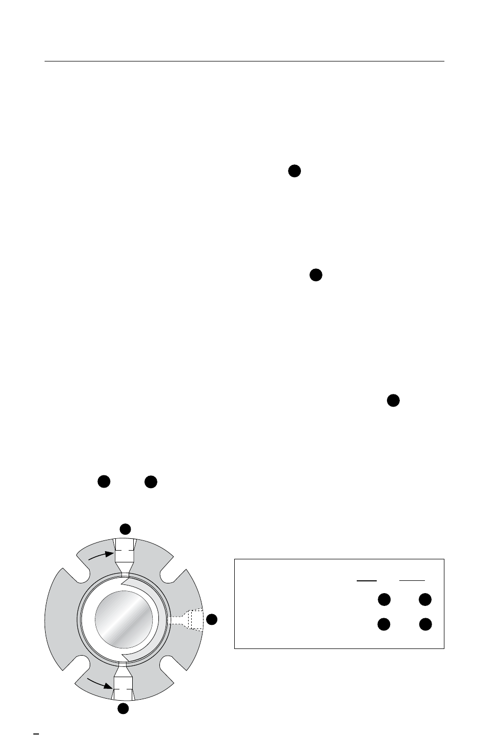
3.4 Taps
b
and
c
in the gland are vent and drain ports used for
fluid quenching, ASME Flush Plan 7362. If they are not used, they
should be plugged with pipe plugs.
Inlet Outlet
Clockwise (CW)
Port
c
Port
b
Counterclockwise (CCW) Port
b
Port
c
CW
Rotation
CCW
Rotation
a
b
c
Figure 7