Flowserve Seal Support Reservoir User Manual
Page 3
3
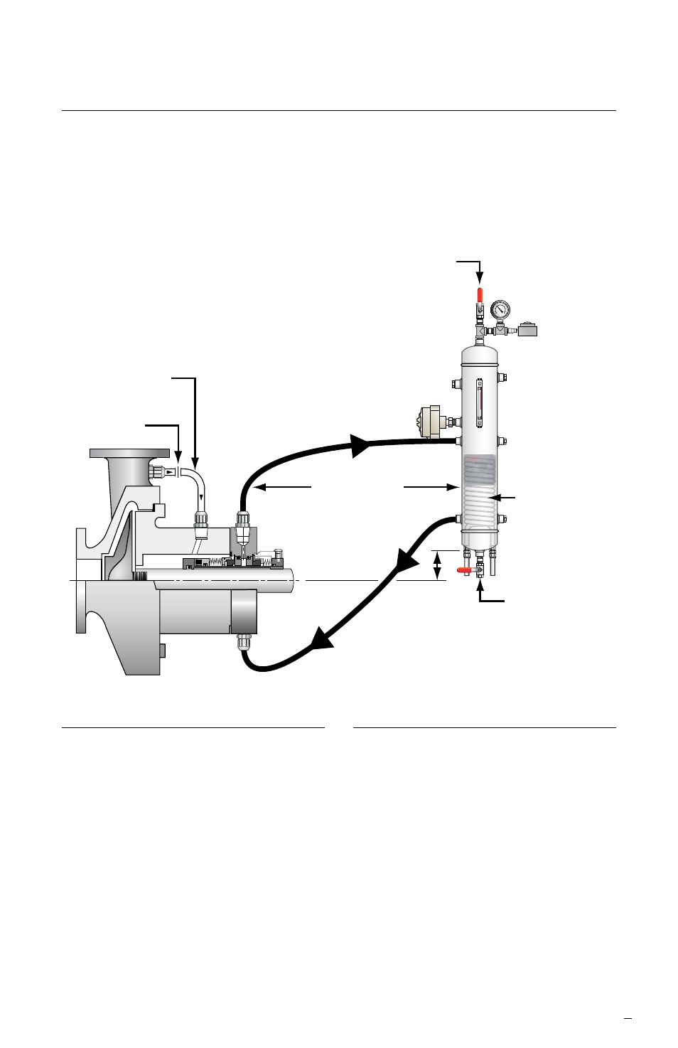
Dual Inside Seal with Induced Circulation
Through Supply Tank with Cooling Coil Figure 1
Plan 53A/ANSI Plan 7353A
Pressure source
4 feet (1.2 m)
maximum
1.5 - 2 feet
(0.45 -0.6 m)
minimum
Orifice
option
Bypass line
from pump
discharge
Supply
tank
assembly
normally open
Level switch (low)
Pressure
switch
(low)
Pressure
indicator
Cooling
coils
Drain
normally
closed
Plan 53B/ANSI Plan 7353B
What
Pressurized barrier fluid circulation
through reservoir.
Fluid is circulated by a pumping ring
in the dual seal assembly
What
Pressurized barrier fluid circulation
with bladder accumulator.
Fluid is circulated by a pumping ring in
the dual seal assembly.
Why
Isolate process fluid.
Zero process emissions.
Higher pressure than Plan 53A.
Plan 53C/ANSI Plan 7353C
What
Pressurized barrier fluid circulation with
piston accumulator.
Fluid is circulated by a pumping ring in
the dual seal assembly.
Why
Isolate process fluid.
Zero process emissions.
Higher pressure than Plan 53A.
Dynamic tracking of system pressure.
Why
Isolate process fluid
Zero process emissions
Typically used <150 psig (10.3 bar) pressure