Flowserve Machinery Components User Manual
Page 10
10
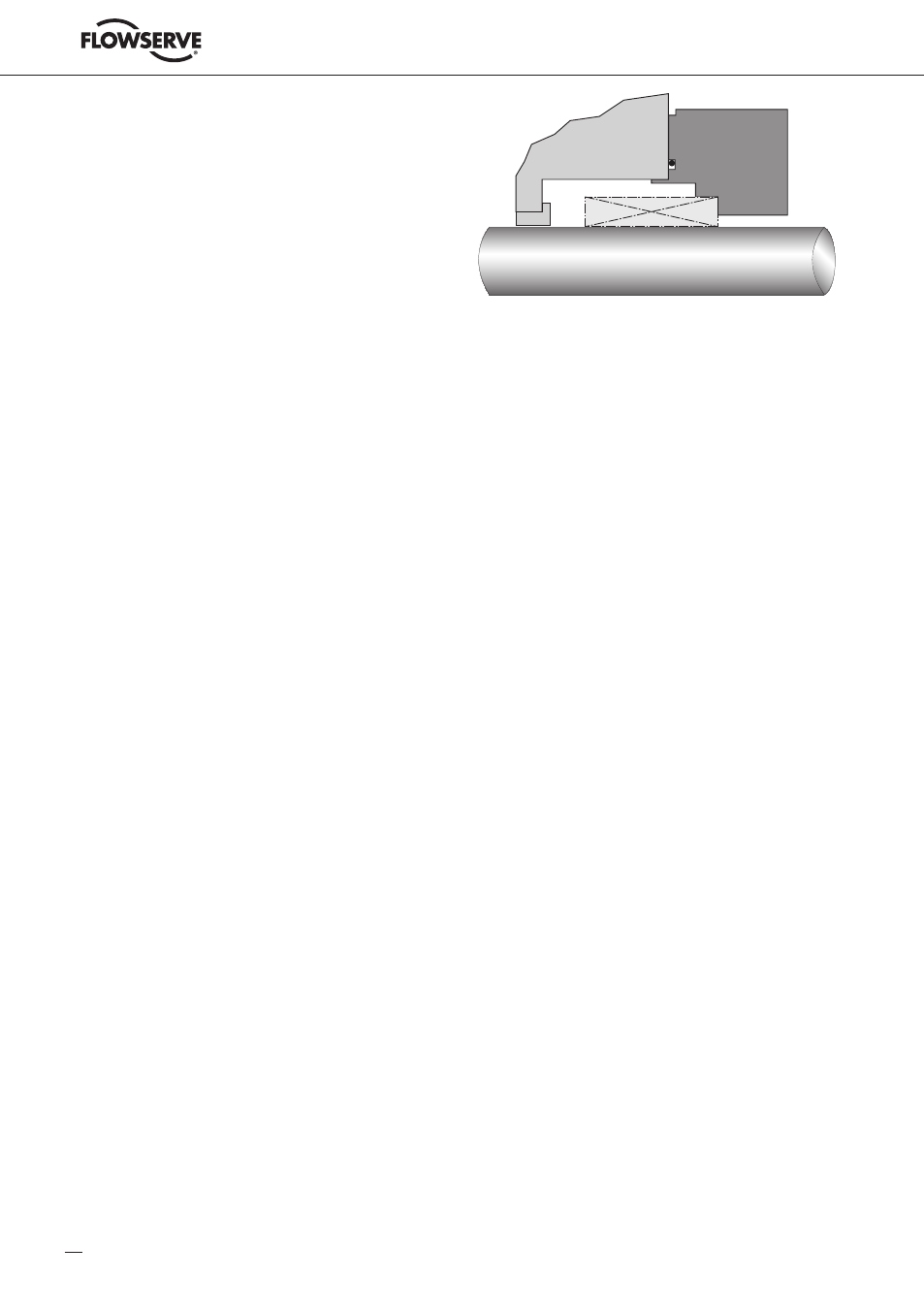
6.3 Installation of a Component Type Seal
See figure 8.
6.3.1 Check assembly drawing, bill of material and seal components prior to installation.
Ensure seal faces and joints are free of scratches, contamination and other damage.
Prior to installation, wipe lapped surfaces clean with a lint free cloth and quick drying
solvent. Lubrication of seal faces is not recommended unless specified on the seal
assembly drawing.
6.3.2 Assemble seal chamber and shaft (including thrust bearings, if applicable) and
verify/scribe the seal setting distance as shown on the assembly drawing. Other
setting aids such as spacer rings may be indicated on the assembly drawing.
Please note that incorrect seal setting can lead to malfunction of the mechanical seal
and consequent leakage of sealed product into the environment.
6.3.3 When applicable, pre-assemble the rotating and stationary components or
sub-components of the seal in accordance with the assembly drawing.
6.3.4 Assemble the seal components sequentially onto the equipment, fastening the rotating
components. Locate the gland(s) against the face of the seal chamber.
6.3.5 Orient the connections on the seal gland(s) as indicated by the seal assembly drawing.
6.3.6 Evenly torque gland bolts/nuts to prevent cocking of the gland or uneven gland pressure
against the seal chamber.
6.3.7 Complete the remaining equipment assembly including thrust bearings, if applicable.
6.3.8 Assemble interconnecting piping as per API-plan and piping instructions as given in
para graph 7. See also (if applicable) auxiliary system installation and maintenance
manual.
6.3.9 Inspect equipment and driver alignment in accordance with coupling and / or equipment
manufacturer's instructions.
6.3.10 After bringing the unit up to operating conditions (pressure and temperature), recheck
pump to driver alignment. Make adjustments as necessary.
!
Figure 8