Mixer/agitator shaft and flange requirements – Flowserve MD-200 Series Durametallic User Manual
Page 3
3
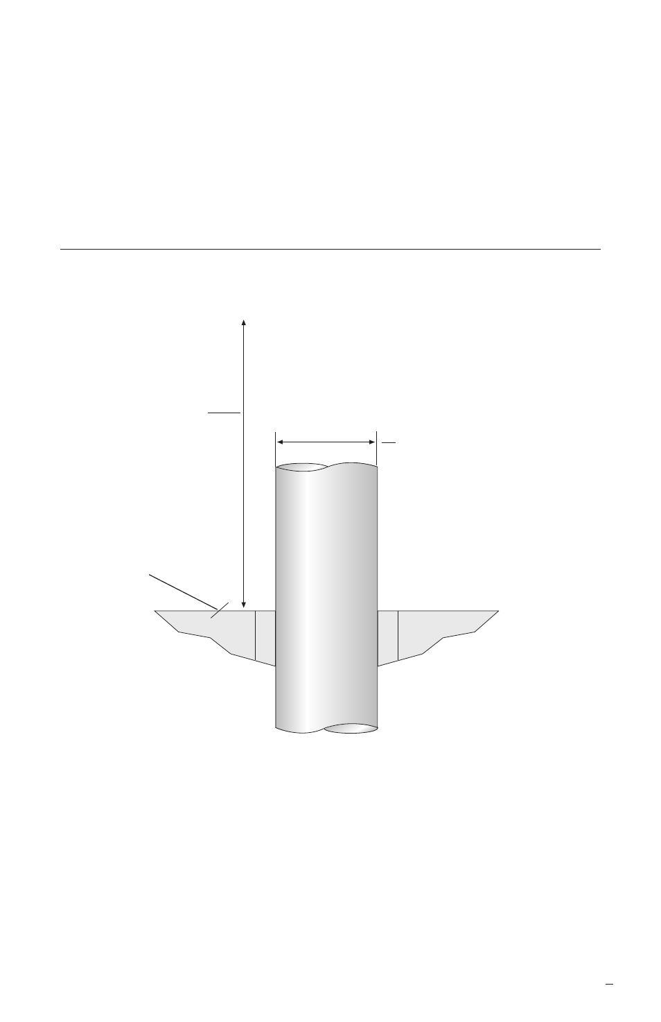
Mixer/Agitator Shaft and Flange Requirements
Figure 1
1.10 Pressure testing of this cartridge canister dual seal prior to
installation is possible using filtered dry nitrogen or instrument air.
Consult Flowserve, Flow Solutions for acceptable gas leakage rates
for this seal design.
To first obstruction
(See assembly drawing)
Face of vessel flange to
be square to the axis of
the shaft to within 0.25 mm
(0.010 inch) FIM and have
a √1.6 µm (63 µinch) Ra
finish or better
• Bearings, drive, and coupling must be in good condition
• Maximum vertical shaft movement (axial end play) = 0.61 mm (0.024 inch) FIM
• Maximum static vessel flange out of concentricity = 0.50 mm (0.020 inch) FIM
• Maximum static vessel flange to shaft out of squareness = 0.25 mm (0.010 inch) FIM
• Maximum dynamic shaft deflection = 3 mm (0.125 inch) FIM
The MD-200 Seal design may include an optional radial bearing in
the canister to protect the seal from excessive shaft runout or whip.
Shaft OD to be +0.025 mm
(+0.001 inch)
-0.025 mm
(-0.001 inch)
with a surface finish of √ 0.8 µm
(32 µinch) Ra or better