1 equipment check, Seal chamber requirements, Figure 1 – Flowserve Q Series BW Seals User Manual
Page 2
2
1 Equipment Check
1.1 Follow plant safety regulations:
• lock out motor and valves.
• wear designated personal safety equipment.
• relieve any pressure in system.
• consult plant MSDS files for hazardous material regulations.
1.2 Adjust the bearings, coupling, and impeller so that the shaft is in its operating
axial position. This shaft position must be used to check all seal setting (SS)
dimensions during installation. Disassemble equipment to allow access to seal
installation area.
1.3 Remove all burrs, nicks or scratches, and sharp edges from the shaft and sleeve
including sharp edges of keyways and threads. Replace worn shaft or sleeve. Make
sure the seal housing bore, face, and sealing fluid flush taps are clean and free of
burrs and sharp edges that might damage gasket.
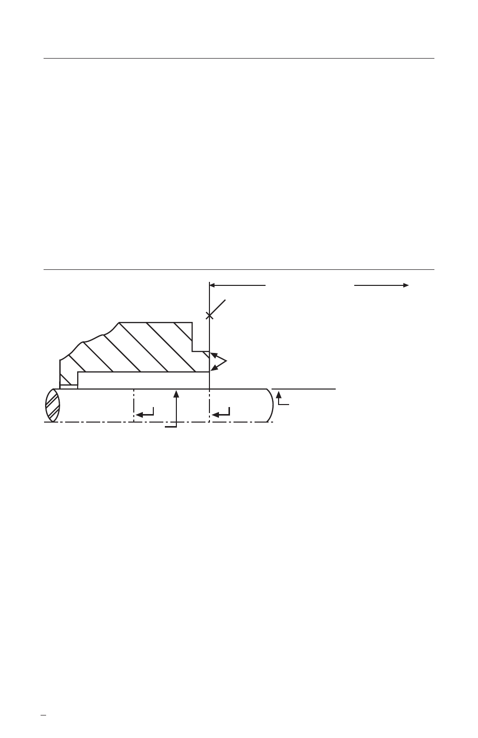
Seal Chamber Requirements
Figure 1
1.4 Check requirements for shaft, sleeve, and seal housing. See Figure 1.
1.5 Check assembly drawing included with the seal for equipment dimensions,
seal design, materials of construction, and piping connections.
1.6 Check shaft or sleeve OD, box depth, box bore, and distance to the first
obstruction to ensure that they are dimensionally the same as shown on the
seal assembly drawing.
1.7 Check gland pilot and bolt holes to ensure they are adaptable to the equipment
and are the same as shown on the assembly drawing.
1.8 Handle all seal parts with care, they are manufactured to precise tolerances.
The seal faces are of special importance. These two sealing faces are lapped flat
to within two light bands (23.2 millionths of an inch).
Keep the seal faces perfectly clean at all times.
To first obstruction
Face of seal housing to be square to the
axis of the shaft to within 0.0005 mm/mm
(0.0005 inch/inch) of seal chamber bore TIR
and have a 1.6
μ
m (63
μ
inch) R finish or better
a
Gland pilot can be at either of these
register locations, concentric to within
0.125 mm (0.005 inch) of shaft or
sleeve OD TIR
Sleeve or shaft finish to be
0.8 μm (32 μinch) R or better
a
Scribe
Mark A
Shaft or sleeve OD
+0.000 mm (+0.000 inch)
-0.050 mm (-0.002 inch)
+0.000 mm (+0.000 inch) API 610/682
-0.025 mm (-0.001 inch) DIN/ISO
• Bearings must be in good condition
• Maximum lateral or axial movement of shaft (end play) = 0.25 mm (0.010 inch) TIR
• Maximum shaft runout at face of seal housing = 0.05 mm (0.002 inch) TIR
• Maximum dynamic shaft deflection at seal housing = 0.05 mm (0.002 inch) TIR
Scribe
Mark B
Seal housing bore to have 3.2 μm
(125 μinch) R finish or better
a
ANSI
The images of parts shown in these instructions may differ visually from the actual
parts due to manufacturing processes that do not affect the part function or quality.