Flowserve ISC2 Single metal bellows seal User Manual
Page 7
7
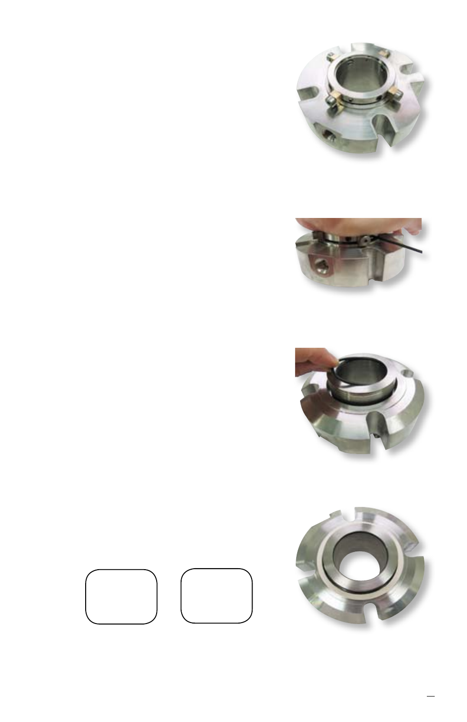
6.14 Perform a dry fit of the collar on the sleeve.
6.15 Install the drive collar [58] onto the sleeve
assembly [1]. The drive collar may need to be
rotated so that the set screws [57] line up with
the large holes and quarter-dog set screws
[57.1] line up with the two smaller holes.
6.16 Install the setting devices and cap screws
[103] and [40] into the drive collar, engaging
with the gland [11]. See Figure 14.
6.17 While compressing seal by pushing down
on gland assembly [11], tighten the quarter-
dog set screws [57.1] to engage into the two
smaller holes of the sleeve assembly [1]. If
the seal does not contain quarter-dog set
screws then install the set screws [57] into the
sleeve [1]. See Figure 15.
Caution:
Over tightening will cause
distortion of the sleeve assembly [1]. Check
integrity of the sleeve with a plug of the
appropriate size to ensure no distortion has
occurred.
6.18 Install O-ring [19] into the ID groove of the
sleeve assembly. See Figure 16.
6.19 The cartridge seal assembly is now ready for
testing.
6.20 Adhere the gland gasket [18] to the gland
gasket surface with a spray adhesive such as
3M Super 77
®
. See Figure 17.
6.21 Permanently mark the seal type ISC2-BX or
ISC2-XB, seal size and gland ring material
clearly on the gland surface. See Figure 1
for placement location.
Figure 14
Figure 15
Figure 16
Figure 17
ISC2-BX
M060
C-276
Example
inch
marking
ISC2-BX
1.875
316 SS
Example
metric
marking