Delta Electronics DVPDNET-SL User Manual
Dvpdnet dvp28sv run stop, Port2 port1, Dvpdnet dvp28sv run stop run stop
http://www.delta.com.tw/industrialautomation/
5011649300-DLE0
2006-12-27
DeviceNet Network Scanner
Instruction Sheet
Warning
This Instruction Sheet only provides descriptions for electrical specifications, general specifications, installation and
wiring.
DVPDNET-SL is an OPEN-TYPE device and therefore should be installed in an enclosure free of airborne dust,
humidity, electric shock and vibration. The enclosure should prevent non-maintenance staff from operating the device
(e.g. key or specific tools are required for opening the enclosure) in case danger and damage on the device may
occur. Do NOT tough any terminal when the power is switched on.
Introduction
Functions:
Support Group 2 server device and Group 2 only
server device.
Support DeviceNet Master mode and Slave mode.
Support EDS file configure in ElinkConfigurator
software.
Support explicit connection via Predefined
Master/Slave Connection Set. (Explicit message)
Connection size is flexible from 1 to 390 bytes in
input and output area.
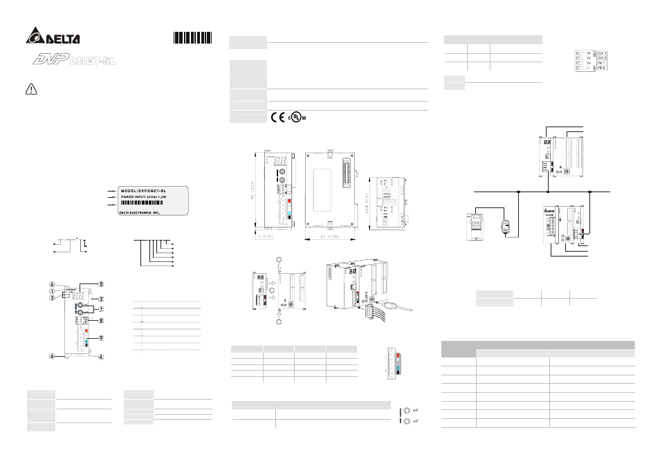
Nameplate Explanation
D NE T-S L 0 T62 600 00 1
M A D E I N XX X XX X
D e l t a P L C m o d e l n a m e
VX.XXXX
P o w e r i n p u t s p e c i f i c a t i o n
B a r c o d e , s e r i e s N o . , v e r s i o n
Model Name and Serial Number Explanations
Serial Number
Production series
Production week
Production year (2006)
Production plant (Taoyuan)
Serial number of version
Production Model
Product Series
For SV MCU
Model
Serial Number
Model type
For SV left side extended module
26 0001
6
T
0
DNET-SL
DVP DNET
S L
Product Profile
Unit: mm
1
Model name
2
Extension port
3
Power, MS, NS LED
4
DIN rail clip
5
Message display
6
Extension clip
7
Address switch
8
Function switch
9
DeviceNet connection port
Specifications
DeviceNet Connection
Interface
Removable connector
(5.08mm)
Transmission
method
CAN
Transmission
cable
2-wire twisted shielded cable
with 2-wire bus power cable
and drain
Electrical
isolation
500V DC
Communication
Message type
I/O polled, bit-strobe, change
of state/cyclic
Baud rates
125 Kbps; 250 Kbps;
500 Kbps
Product code
64
Product type
12
Vendor ID
799 (Delta Electronics Inc.)
Electrical Specification
Module power voltage: All other power derived from PLC controller power supply
DeviceNet
Network power input: 11 ~ 25V DC; Current: less than 50mA (25V DC)
Environment Specifications
Noise immunity
ESD (IEC 61131-2, IEC 61000-4-2): 8KV Air Discharge
EFT (IEC 61131-2, IEC 61000-4-4): Power Line: 2KV, Digital I/O: 1KV,
Analog & communication I/O: 1KV
Damped-Oscillatory Wave: Power Line: 1KV, Digital I/O: 1KV
RS (IEC 61131-2, IEC 61000-4-3): 26MHz ~ 1GHz, 10V/m
Environment
Operation: 0ºC ~ 55ºC (temperature); 50 ~ 95% (humidity); pollution degree 2
Storage: -40 ºC ~ 70ºC (temperature); 5 ~ 95% (humidity)
Vibration/shock
resistance
Standard: IEC1131-2、IEC 68-2-6 (TEST Fc)/IEC1131-2 & IEC 68-2-27 (TEST Ea)
Approvals
Installation
Profile (Dimensions are in millimeter and [inch])
3
2
0
1
4
9
8
6
7
0
MS
NS
5
DR 0
DR 1
x10
IN 1
IN 0
DVPDNET
x10
5
3
2
4
0
1
8
6
7
9
1
Installing DVPDNET-SL With PLC MPU
DVPDNET
DVP28SV
RUN
STOP
2
2
1
Pin Definition Of DevicetNet Connection Port
Pin
Signal
Color
Content
1
V-
Black
0 VDC
2 CAN_L
Blue
Signal-
3 Drain - Shield
4 CAN_H
White
Signal+
5 V+
Red
24
VDC
1
2
3
4
5
MAC ID Setting
Switch setting
Content
0…63
Valid DeviceNet MAC ID setting
Others
Invalid DeviceNet MAC ID setting
9
1
6
4
5
0
0
9
1
3
2
7
8
2
5
6
4
3
7
8
Function Switch Setting
DR1
DR0
Baud rate
OFF OFF
125K
bps
OFF ON
250K
bps
ON OFF
500K
bps
IN0
Reserved
IN1
Reserved
Connecting DVPDNET-SL Scanner With Slave Devices
Connection Example:
PORT2
PORT1
DeviceNet
DVP-PS01
VFD-B
DNA02
DVPDT01
DVP-12SC
DVP28SV
DVPDNET-SL
DVPDNET
DVP28SV
RUN
STOP
RUN
STOP
D
V
P
-1
2
S
C
D
T
0
1
L
N
0V
Cable Length and Baud Rates
The maximum cable length in a segment depends on the transmission speed. DeviceNet communicates at
speeds from 125K bps to 500K bps over distances from 100 to 500 meters.
Baud rates (bps)
125K
250K
500K
Length (m)
500
250
100
Configuration
Access DNET Scanner With PLC
When DNET scanner is connected to PLC, it will get a data area that maps to DNET scanner in PLC.
Mapped D registers
Index of DNET
scanner
Output image table
Input image table
1
D6250 – D6497
D6000 – D6247
2
D6750 – D6997
D6500 – D6747
3
D7250 – D7497
D7000 – D7247
4
D7750 – D7997
D7500 – D7747
5
D8250 – D8497
D8000 – D8247
6
D8750 – D8997
D8500 – D8747
7
D9250 – D9497
D9000 – D9247
8
D9750 – D9997
D9500 – D9747
The index of DNET scanner is the sequence number of scanner. The 1
st
scanner is near to SV MPU and the index number is1. The 2
nd
scanner is
near to the 1
st
scanner in the left side and to be numbered as 2. The others are numbered as 3, 4, …and so on.