DFI EL330-DR User Manual
Page 23
23
2
Hardware Installation
1
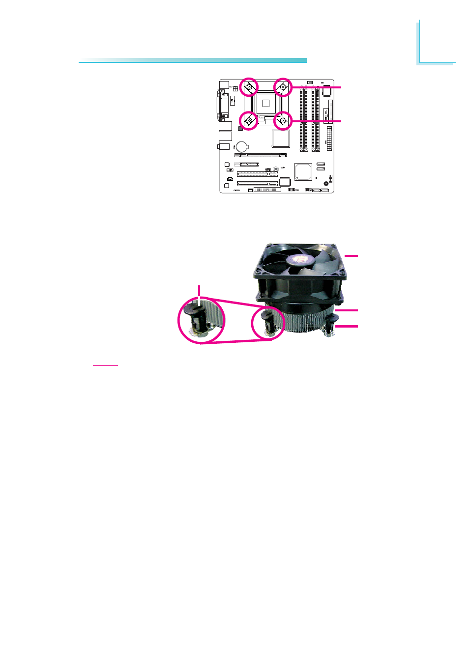
Fan
Heat sink
Stud
Groove
2. Place the heat sink on top
of the CPU. The 4 studs
around the heat sink which
are used to secure the
heat sink onto the system
board must match the 4
mounting holes around the
socket.
Position each stud so that
the groove faces the heat
sink then push it down
firmly until it clicks into
place.
Note:
You will not be able to secure the fan and heat sink assembly in place
if the groove is not facing the heat sink.
3. Connect the CPU fan’s cable connector to the CPU fan connector on
the system board.
Mounting hole
Mounting hole
See also other documents in the category DFI Motherboard:
- AR100-DR (112 pages)
- G7B630-N (127 pages)
- G7B630-N (154 pages)
- BT100 (71 pages)
- HR100-CRM (170 pages)
- BT103 (72 pages)
- BT161 (71 pages)
- CM100-C (70 pages)
- CD101-N (69 pages)
- CD102 Series (76 pages)
- CP100-NRM (150 pages)
- CR101-D (67 pages)
- CR100-CRM (177 pages)
- EL339-B (109 pages)
- G5C100-NR (160 pages)
- HD100-H81 (79 pages)
- HD101-H81 (83 pages)
- HD173-H81 (70 pages)
- HM100-QM87 (97 pages)
- HM103-QM87 (99 pages)
- HU103 (95 pages)
- KB161 (68 pages)
- HU173 (90 pages)
- LR100-N18M/N18S (126 pages)
- LR102-B18M (138 pages)
- EL630-NR (149 pages)
- NP101-D16C (150 pages)
- SB102-D (60 pages)
- NP102-N16C (144 pages)
- MB630-CRM (171 pages)
- SB630-CRM (184 pages)
- SB630-CRM (183 pages)
- SR100-L20C (144 pages)
- SR100-N (152 pages)
- LT600-L (149 pages)
- G7B630-N (147 pages)
- CA331-P (131 pages)
- CP337-NRM (174 pages)
- HD310-Q87 (101 pages)
- EL620-C (192 pages)
- G7L630-B (133 pages)
- HD330-H81 (81 pages)
- HD330-Q87 (85 pages)
- HD332-H81 (76 pages)