Chapter 2 – DFI COM101-BAT User Manual
Page 20
www.dfi .com
Chapter 2 Hardware Installation
20
Chapter 2
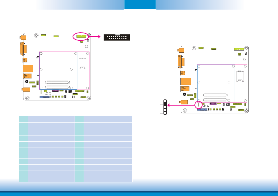
Digital I/O Connector
The 8-bit Digital I/O connector (4-bit GPI and 4-bit GPO) provides powering-on function to the
external device that is connected to the connector. The pin functions of the Digital I/O connec-
tor are listed below:
Pins
Pin Assignment
Pins
Pin Assignment
1
GND
2
+12V
3
DIO7 (GPO3)
4
+12V
5
DIO6 (GPO2)
6
GND
7
DIO5 (GPO1)
8
+5V
9
DIO4 (GPO0)
10
+5V
11
DIO3 (GPI3)
12
GND
13
DIO2 (GPI2)
14
+5V_Standby
15
DIO1 (GPI1)
16
+5V_Standby
17
DIO0 (GPI0)
18
GND
19
GND
19
1
2
Digital I/O
S/PDIF Connector
5
1
+5V
Key
SPDIF out
Ground
SPDIF in
S/PDIF
The S/PDIF connector is used to connect external S/PDIF ports. Your S/PDIF ports may be
mounted on a card-edge bracket. Install the card-edge bracket to an available slot at the rear
of the system chassis then connect the audio cable to the S/PDIF connector. Make sure pin 1
of the audio cable is aligned with pin 1 of the connector.
- ES300 (2 pages)
- U340 Series (2 pages)
- VS Series (2 pages)
- BT9A3 (57 pages)
- CD9A3 series (60 pages)
- CD905-B series (68 pages)
- BT700 (71 pages)
- BT700 (71 pages)
- CD905-B2600 (63 pages)
- CD905-B2800 (63 pages)
- CP908-B (104 pages)
- CR908-B (68 pages)
- HR908-B (66 pages)
- HU968 (86 pages)
- ML905-B11C/B16C (76 pages)
- KB968 (68 pages)
- LR905-B18S (93 pages)
- OT905-B series (61 pages)
- CM960-B (1 page)
- CM901-B (72 pages)
- CP900-B (130 pages)
- NP905-B16C (125 pages)
- CR900-B (73 pages)
- CR902-BL (75 pages)
- CR901-B (69 pages)
- CR960-QM77 (81 pages)
- HM920-QM87 (98 pages)
- G5C900-B106 (118 pages)
- HM960-QM87 (101 pages)
- HM961-QM87 (95 pages)
- HR900-B (102 pages)
- HR902-BL (75 pages)
- FS700 (17 pages)
- QB702-B (47 pages)
- QB700-B (73 pages)
- COM100-B (32 pages)
- QB701-B (73 pages)
- NP900-B16C (121 pages)
- COM630-B (50 pages)
- COM330-B (57 pages)
- Q7-100 (31 pages)
- Q7-951 (46 pages)
- Q7A-551 (23 pages)
- Q7X-151 (30 pages)