Installation, 1 general system, 2 beam and footing selection – Daktronics CH-1436H User Manual
Page 7: Installation -1, General system -1, Beam and footing selection -1
Installation
2-1
Section 2 : Installation
2.1 General
System
Reference Drawings: Color Code, 25-Pin J-Box............................ Drawing A-47207
Connector Plate, CH-1436H ....................... Drawing A-63501
Installation Specifications, CH-1436HH ...... Drawing A-63502
System Layout, CH-1436H ......................... Drawing A-63503
Mounting Instructions, CH-1436H ............... Drawing A-63504
Component Locations, CH-1436H .............. Drawing A-63922
Power & Signal Entrance, CH-1436H ......... Drawing A-63923
Refer to Drawing A-63503 for a general system layout.
The general procedure for installing the CH-1436H display is as follows:
1. Select beam and footing recommendations from the table below.
2. Dig the footing holes and install beams and footings.
3. Route power and signal cables to the display and control locations.
4. Mount the displays to the beams as described in Section 2.3 and Drawings A-63502 and
A-63504.
5. Route power and signal wires into the displays as described in Section 2.4 and Drawings
A-47207, A-63501, A-63922 and A-63923.
2.2
Beam and Footing Selection
Reference Drawing: Mounting Instructions, CH-1436H ................. Drawing A-63504
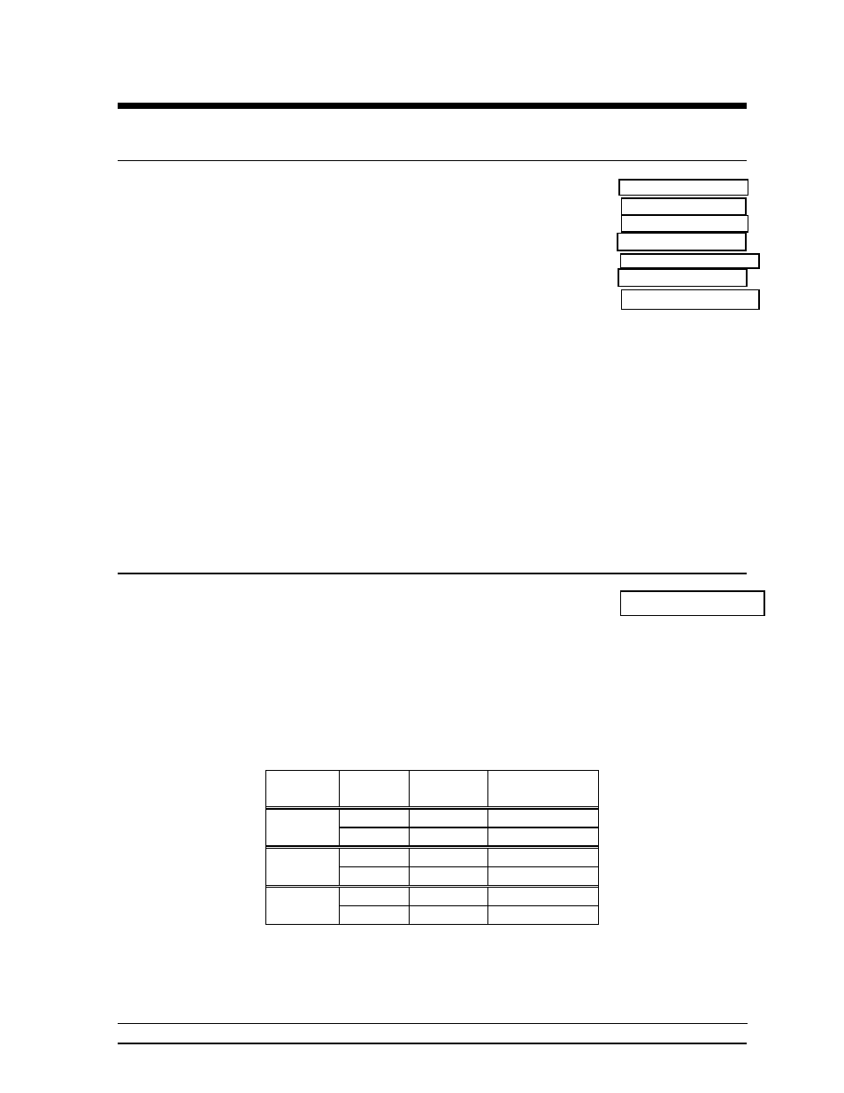
The table below contains recommendations for W-shape beams and footings to support the
display as shown in Drawing A-63504. The first column is wind velocity in miles per hour.
The distance in the second column is from the ground to the bottom of the display. The
choice from these columns depends upon the display location.
The beams listed below are beams which provide maximum wind load strength for the weight
and cost of the beams.
Wind
Speed
Height
(ft)
Beam
Section
Footing
Depth x Dia.
70 mph
10
W8 x 15
4 ¾ ft x 3 ft
15
W6 x 20
5 ½ ft x 3 ft
80 mph
10
W8 x 15
5 ½ ft x 3 ft
15
W8 x 20
6 ¾ ft x 3 ft
90 mph
10
W8 x 17
6 ¼ ft x 3 ft
15
W8 x 24
7 ft x 3 ft
The calculations for footing diameters and depths are based on the assumption that footings
are in undisturbed soils, not fill soils. Lateral bearing capacity of 300 psf per foot of depth in
natural grade was used to derive these figures.