2 power wiring, 2 power wiring -3 – Daktronics CH-1018V User Manual
Page 9
Installation
2-3
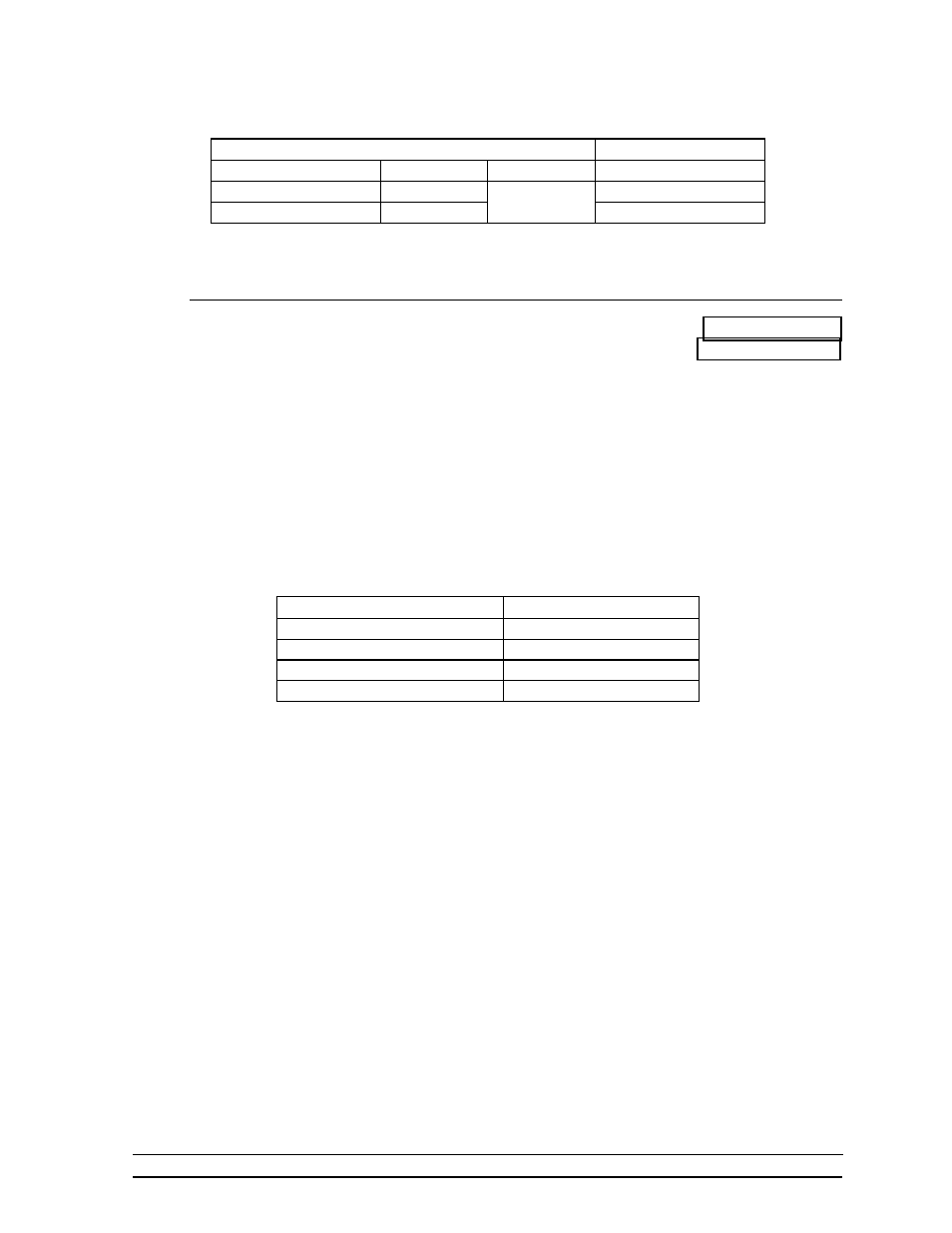
to Drawing A-37915 for an illustration of the components inside the entrance
enclosure. Connect the signal wires to TB31 as indicated in the table below.
Control End
Display End
J-box Terminal No.
Wire Color
Output No.
TB31 Terminal No.
14 Red/Wht
1*
1
(+)
15 Grn/Wht
2
(-)
*Auxiliary display(s) require(s) a different output no.(s). Consult your CHTS-300 console
manual.
2.4.2 Power Wiring
Reference Drawings: Driver Enclosure, Power & Signal.... Drawing A-37915
Electrical Installation, CH-1018V..... Drawing A-55699
A 120/240 VAC circuit (two hot lines, one neutral, plus a ground) must be run into a
load center. Refer to Drawing A-55699. With all lamps lighted, this display is
capable of drawing a maximum of 40 amps on one line and 14 amps on the other line.
Route four “hot,” two “neutral,” and one “ground” wire, 12 AWG from the load
center (refer to Drawing A-55699) to the driver enclosure (refer to Drawing A-
37915) in the display. Refer to Drawing A-37915 for component locations at the
driver. Connect the ground wire to terminal E41. Connect the two neutral wires to
TB41-3 and TB41-4. Connect the hot wires to the load center and the display as in
the example below.
Load Center Breaker No.
Display Terminal No.
1 TB41-1
2 TB41-2
3 TB41-5
4 TB41-6
Note: Breaker numbers are suggestions only and may be assigned as required. The
objective is to have TB41-1 and TB41-2 on line 1. TB41-5 and TB41-6 should be on
line 2.