Daktronics, inc – Daktronics Labelle GL100 User Manual
Page 2
ED-8969
Page 1 of 2
DAKTRONICS, INC.
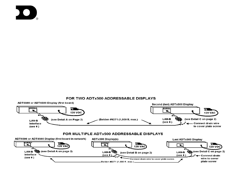
LAN-B NETWORK DIAGRAM FOR ADTx500 DISPLAYS
The LAN-B bi-directional network is used in applications where an ADT6500 or ADT4500 will be used to transmit messages to other ADTx500s.
NOTE: the ADT3500 model can only receive messages or relay messages to other ADTx500 displays. It cannot initiate a message transmission.
IMPORTANT: Each LAN-
B interface box has a “BIAS” switch. One and ONLY ONE of the LAN-B boxes (usually the one connected to
the first display in the network) must have its BIAS switch set to the ON position. All the other LAN-B interface boxes must have their
BIAS switches set to the OFF position. The ADTx500 display network will not operate correctly If these BIAS switches are not set as
described and illustrated here. Also, 120 Ohm terminating resistors must be installed at the first and last displays in the net work.
For ADT6500 or ADT4500 displays, use interface box LAN-B/DB9, which has a DB9 (9-pin) connector. For ADT3500 displays, use LAN-
B/TEL, which as a DB9 with an RJ-45 Telco (phone plug-style) adapter. Use Belden #9271 shielded, twisted pair wiring (or equivalent) for the
network run. Be sure to connect one and only one end of each Belden #9271 section’s drain (shield) wire to an earth ground (a screw on the
display, for example).
If you are using ADT3500 displays in your network, make sure each display’s #2 DIP switch (located under the INTERFACE MODULE cover
plate) is set to the ON position. Refer to the ADT3500 DIP switch setting instructions and diagram on the following page.